The following information is provided for reference purposes only and should be used at your own risk
In no event shall Beisan Systems, LLC or its members be liable for incidental, consequential, or special loss or damages of any kind however caused.
Introduction
“Vanos” is BMW’s name for its variable valve timing units. Vanos units take on various shapes and design according to car year and model (engine model). The vanos discussed here is BMW part # 11-36-1-404-701. It’s a double vanos; meaning the intake and exhaust valve timing is varied. This vanos unit is part of BMW 6-cylinder engine Euro S50B32. This engine was incorporated into three car models, the 3-series Euro E36 M3 96-99, Euro Z3 M Coupe 98-00, and Euro Z3 M Roadster 96-00.
This vanos has been experiencing a failure. It has been diagnosed that the failure is primarily due to deterioration of the vanos intake rod seal. It has been determined that this cup seal is made from Buna rubber (Buna-N, NBR, Nitrile). Buna is a very common rubber material, but is limited in its temperature and chemical resistance characteristics. Unfortunately it is fairing quite badly in the vanos/engine environment. The seal has been found to harden, shrink, and have flat surfaces. This deterioration is causing the seal to lose its functional characteristics and thus cause the vanos to fail. BMW has been engaged regarding other vanos failures in the past but has elected to not address the issues, “No further development will be done”. BMW does not provide the vanos rod seal as a separate part.
The Buna rod seal can be replaced with a Viton rubber rod seal. Viton (FKM, Fluorocarbon) has similar functional characteristics to Buna, but has much higher temperature and chemical resistance characteristics. But an even better solution is to replace the rod seal with a Teflon equivalent. Teflon (PTFE filled) has a much lower friction property and is more appropriate for dynamic sealing than rubber. It’s compatible with the engine environment and is a standard material for this rod cup seal design. An O-ring is inserted in the cup to provide energizing support for the Teflon. The O-ring is best made from Viton to handle the engine environment.
The vanos intake piston seal can also in some cases experience a problem. This seal is made of a Teflon ring and a backing machined Viton rubber ring. It can lean to one side and the Teflon ring wears unevenly. This problem is caused by two factors. First, the rod seal failure causes leakage from an oil chamber on one side of the piston seal and the oil chamber on the opposite side of the piston seal presses against the seal and tilts it. Second, the piston seal cavity is too wide and facilitates the space for the seal to tilt. This is caused by the introduction of a paper gasket between two piston parts that widens the cavity. This paper gasket functions to maintain the piston parts from spinning during assembly, but has no function after assembly.
The piston seal problem can be solved by replacing the rod seal with a seal that doesn”t fail and allow the oil chamber leak, and the removal of the paper gasket to return the piston seal cavity to the correct width and remove the excess space.
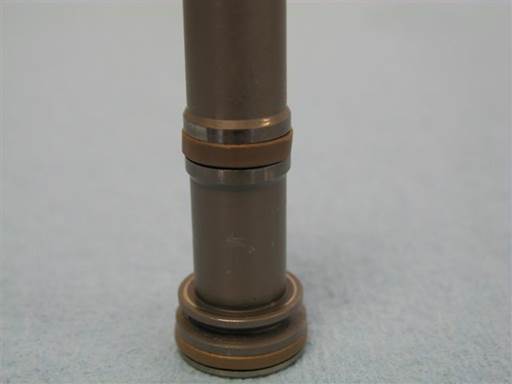
The vanos exhaust piston seals can also fail in their function. There are two piston seals and each is made of a Teflon ring with a backing Viton O-ring. The failure is due to loose seal fit. This seems to be caused by a combination of some Teflon material wear and O-ring compression set (flattening).
The Teflon filler material is Bronze and is correct for this vanos application. Viton comes in variations of materials and some are less susceptible to compression set.
The piston seals problem can be solved by slightly thickening the Teflon rings and using Viton O-rings that are less susceptible to compression set. The Beisan sourced Viton O-rings have been shown over time to have excellent compression set characteristics.
The vanos solenoid O-rings also fail and in some cases and cause external oil leak. These O-rings are made from Buna and harden and flatten.
Replacing the O-rings with Viton O-rings has proven to not work. The Viton O-rings shred from the high oil pressure. BMW has redesigned the solenoid O-rings for the S62 engine (E39 M5) vanos unit. The S62 vanos solenoids are the same as the Euro S50 vanos solenoids and share the same O-rings. The new S62 solenoid O-rings are not only made from Viton but also have multiple facets. These facets function to divert oil flow away from the O-ring and keep it from shredding.
The new S62 vanos solenoid O-rings are the correct design and can be used for this vanos solenoid O-rings. These are purchased directly from BMW and are not provided in the Beisan seals kit.
The vanos also has multiple O-rings used for static sealing. The O-rings, with the exception of one, are made from Viton, which is the correct material. But over time they experience compression set (flattening) and need replacement.
The static sealing O-rings can be replaced with a set of Viton O-rings.
A vanos seals/O-rings repair kit can be acquired through Beisan Systems (bee-saan), www.beisansystems.com/products. It includes a vanos replacement intake rod Teflon cup seal with inserted Viton O-ring, intake piston seal of Teflon ring and machined Viton rubber ring, exhaust piston seals with slightly thickened Teflon rings and backup Viton O-rings, and a replacement set of the static Viton O-rings.
Symptoms
Cars experience:
Overall loss of torque and power, particularly in the lower RPM range, < 3k. Bogging then surging at 3k RPM. Uneven power distribution and RPM transition. Engine hesitations in the lower RPM range, < 3k. Louder idle and intermittent idle RPM hiccups. Difficult takeoffs. Loss of power and bogging when AC on. Increased fuel consumption.
Repairing the vanos seals provides:
Overall increase in torque and power, particularly in the lower RPM range, < 3k. Resolution of bogging then surging at 3k RPM. Smooth even distribution of power and RPM transition. Resolution of engine hesitations in the lower RPM range, < 3k. Quiet stable idle. Smooth easy takeoffs. Improved performance when AC on. Reduced fuel consumption.
Diagnosis
In general, a diagnosis is not necessary. The vanos Buna intake rod seal deteriorates in 20k miles (32k kilometers). Thus essentially all the cars with this vanos have deteriorated intake rod seal and a failing vanos.
Repair Procedure
The following is a Euro E36 M3 double vanos seals R&R (remove and replace) procedure.
The valve cover gaskets and bolt grommets on the Euro S50 engine are made from Viton and thus do not fail and need replacement.
Repair time: 5 hours mechanic, 7+ hours DIY.
Parts, Tools, and Shop Supplies
Parts with part number pattern xx-xx-x-xxx-xxx are BMW parts and can be acquired from a BMW dealership.
Beisan Systems only provides the vanos seals repair kit.
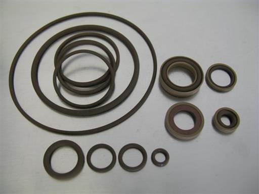
Euro S50 double vanos seals repair kit (BS041) $80/each (www.beisansystems.com)
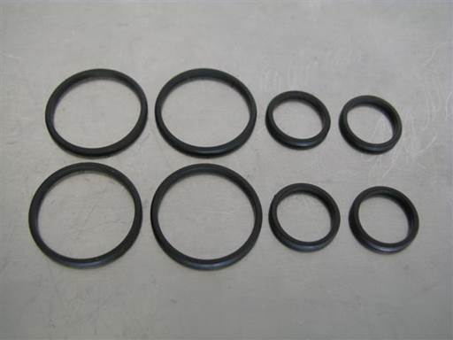
4 x large solenoid O-ring (11-36-7-830-828) $2.29/each, 4 x small solenoid O-ring (11-36-7-830-829) $3.38 / each
Note: BMW solenoid O-rings are from BMW S62 (E39 M5) vanos. These O-rings have been redesigned to have multiple facets to avoid high oil pressure shredding and are made from Viton to resist engine high temperature and synthetic oil.
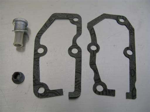
Vanos oil filter (11-36-1-401-973) $16.27/each, vanos oil filter washer (07-11-9-963-073) $.09/each
Vanos intake solenoid cover gasket (11-36-1-402-659) $7.84/each, vanos exhaust solenoid cover gasket (11-36-1-404-154) $7.84/each
Intake splined shaft and piston self-locking nut (11-36-1-313-170) $5.42/each
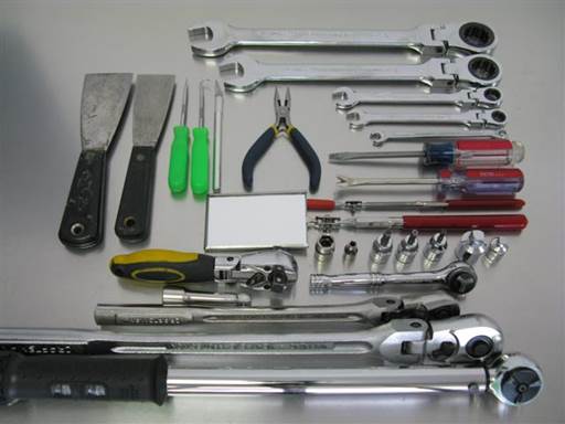
2 x putty-knife (small, medium)
Strait pick, hook pick, 90 degree pick, razor knife, medium nose pliers (small)
24mm combo wrench (not shown), 22mm combo wrench, 12mm combo wrench, 10mm combo wrench, 7mm combo wrench
Flathead screwdriver (medium head), tack lifter, magnet pickup, mirror (medium)
24mm socket 1/2″, 10mm socket 3/8″, 4mm socket (6 point) 1/4″, 6mm hex bit socket 3/8″, 5mm hex bit socket 3/8″, 4mm hex bit socket 3/8″, 1/2″ to 3/8″ socket adapter, 3/8″ to 1/4″ socket adapter
1/2″ ratchet, 3/8″ ratchet, 1/4″ ratchet, 1/2″ long-arm ratchet, 3/8″ long-arm ratchet
3/8″ socket extension (short)
Torque wrench (5 Nm [4 ft-lb], 12 Nm [9 ft-lb])
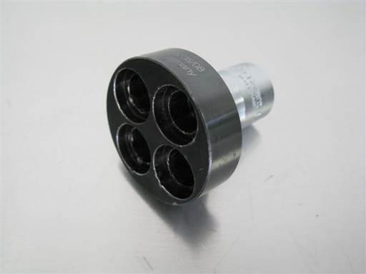
BMW crankshaft turning socket (83-30-0-491-056) $68.04/each
Note: Can be substituted with 36mm 12-point socket 1/2″
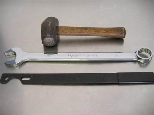
Mechanical fan removal tools:
32mm combo wrench, BMW water pump pulley holder (83-30-0-491-046) $37.76/each
Handheld sledge hammer (3lb)
Note: Water pump pulley holder is available from aftermarket vendors, often found on ebay. It is usually listed under its original BMW part 115030. It is often also available in a combination tool set with a 32mm slim open wrench.
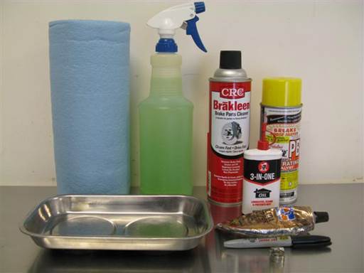
Paper towels, water based cleaner (simple green 1:10), brake cleaner, spray lubricant, assembly oil (lubricant oil)
Parts plate, gasket sealant, magic marker, small house clamp (smallest standard).
Repair
Car engine must be cold to perform repair procedure.
Right and Left denotations are from car front at hood orientation.
Removal of fan & shroud
Euro E36 M3 fan & shroud removal
Removal of valve cover
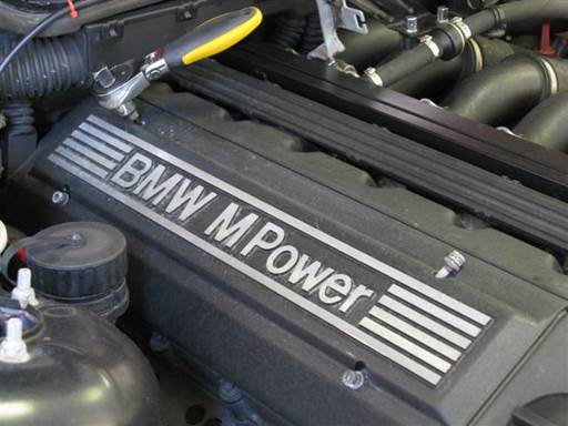
Remove engine top cover.
Remove 4 cover mounting bolts (5mm hex bit socket 3/8″ / 3/8″ ratchet).
Remove cover.
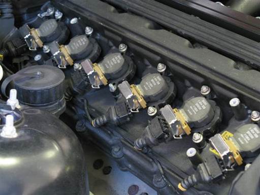
Disconnect ignition coils electrical cable connectors.
For each coil, pull up on coil connector metal lock and pull off electrical cable connector.
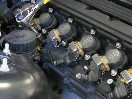
Remove coil electrical cables mounting bracket.
Remove bracket 2 mounting nuts (10mm socket 3/8″ / 3/8″ ratchet & extension).
Remove bracket from mounting studs.
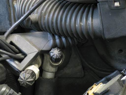
Remove coil cables rear boot rubber block from valve cover.
Rotate cables/bracket/boot to side and wedge boot between air conditioning valve stem and upper cable harness boot.
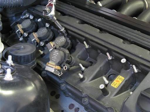
Remove coils.
Remove 2 mounting nuts at each coil (10mm socket 3/8″ / 3/8″ ratchet & extension).
Pull up and out all coils.
Note: Maintain coil/cylinder association for reinstallation. This is not necessary, but is good practice.
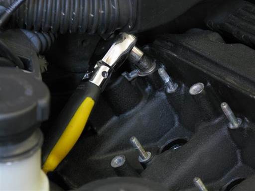
Remove valve cover ground wire from rear valve cover.
Remove mounting nut (10mm socket 3/8″ / 3/8″ ratchet).
Remove ground wire from valve cover stud and set to rear.
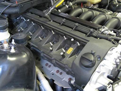
Remove 16 valve cover mounting bolts w/ grommets at perimeter of valve cover (10mm socket 3/8″ / 3/8″ ratchet & extension, tack lifter).
Note: Rear center bolt has limited access (10mm socket 3/8″ / 1/2″ ratchet & 1/2″ to 3/8″ socket adapter (extension), tack lifter).
Note: Front center bolt is short.
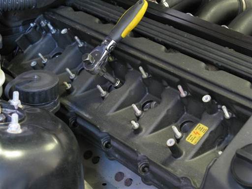
Remove 4 valve cover mounting bolts w/ grommets at center of valve cover (10mm socket 3/8″ / 3/8″ ratchet & extension, tack lifter).
Note: Bolts are short.
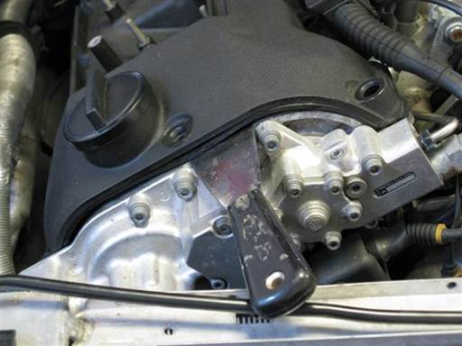
Remove valve cover from engine head.
Insert blade (medium putty-knife) between valve cover gasket and engine head and pry up at all front end accessible locations to break gasket bond. Be sure to break gasket sealant bond at front corners.
Repeat blade insertion and prying until cover gasket seize breaks and cover lifts. Notable prying might be needed at front center to break seize.
Note: If valve cover can not be removed, double check valve cover 16 perimeter bolts and 4 center bolts have been removed.
Lift up and remove valve cover from engine head.
Remove valve cover perimeter gasket.
Remove valve cover sparkplug well gaskets.
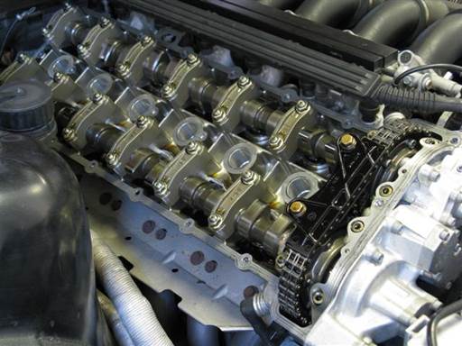
Removal of vanos
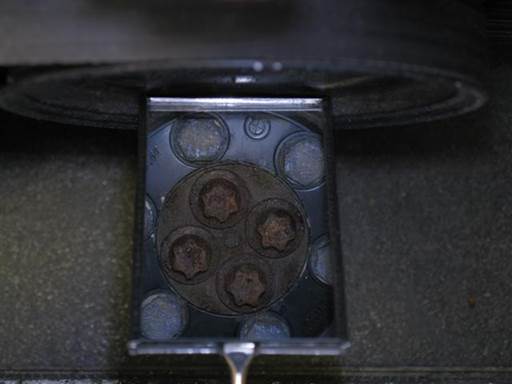
Locate 4 center torx bolts on crankshaft pulley (mirror).
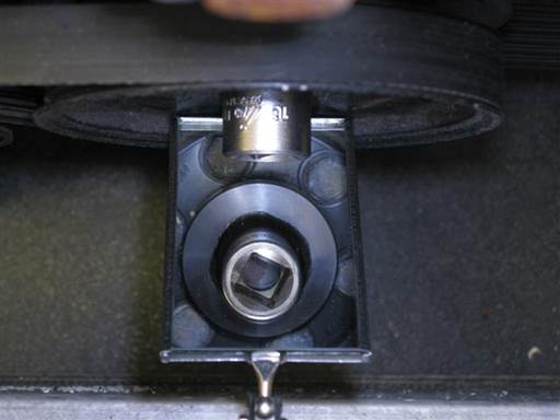
Mount crankshaft turning socket on crankshaft pulley 4 center torx bolts (mirror).
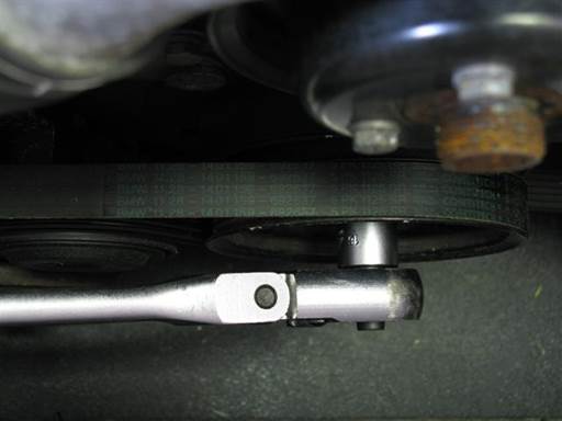
Mount ratchet on crankshaft turning socket (1/2″ long-arm ratchet).
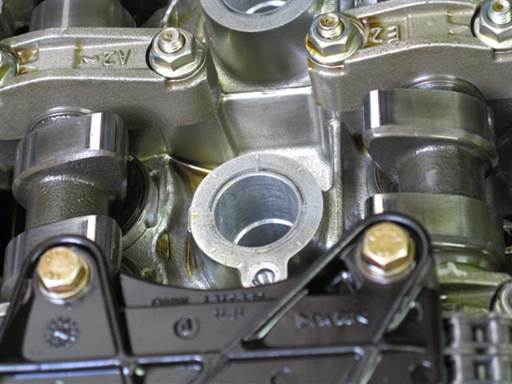
If manual transmission, place transmission in neutral. This allows turning of crankshaft.
Turn crankshaft pulley clockwise until cylinder 1 intake and exhaust cams point to each other at ~45 degree angle (crankshaft turning socket / 1/2″ long-arm ratchet).
Note: Turning crankshaft counter clockwise is acceptable.
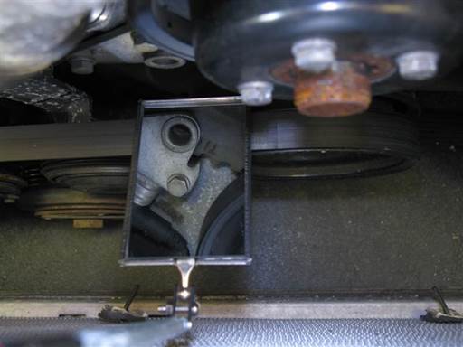
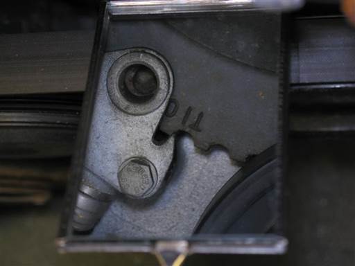
Inspect TDC (top dead center) timing marks on engine timing cover and crankshaft harmonic balancer at ~11 o”clock position (mirror).
Adjust crankshaft pulley to align TDC timing marks (crankshaft turning socket / 1/2″ long-arm ratchet).
Note: Align pointer on timing cover bracket with 1 mark on harmonic balancer.
Note: If timing marks on harmonic balancer not visible they might be hidden behind water pump pulley. Turn crankshaft pulley counter clockwise.
Note: Precise alignment is not necessary.
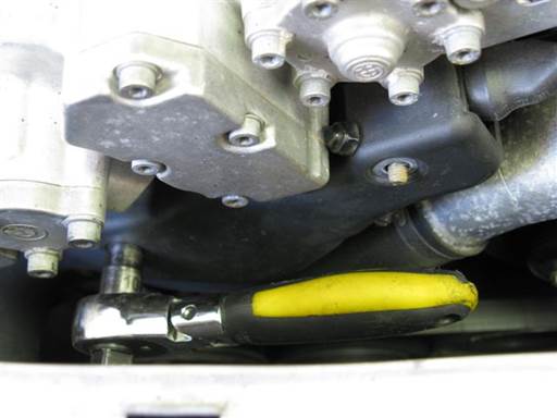
Remove vanos electrical connectors cover.
Remove cover 2 mounting nuts (10mm socket 3/8″ / 3/8″ ratchet).
Remove cover.
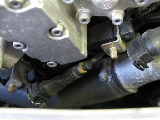
Disconnect vanos intake and exhaust solenoid electrical cable connectors.
Press in connector wire clip and pull off connector.
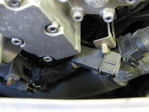
Remove vanos intake and exhaust solenoid electrical cable connectors from mounting brackets.
Pull out connectors from brackets.
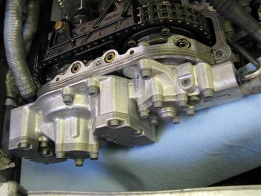
Insert double length double layer towel under vanos and rest on thermostat and radiator lower hose (towels).
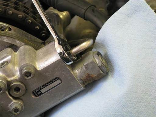
Remove vanos oil accumulator pipe from vanos.
Remove oil pipe mounting bolt (12mm open wrench).
Pull out oil pip from vanos and set above vanos (next picture).
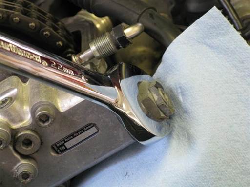
Slightly loosen vanos oil pressure restrictor (22mm open wrench).
Note: Pressure restrictor work will be performed at bench. Loosening is easier to perform while vanos is mounted.
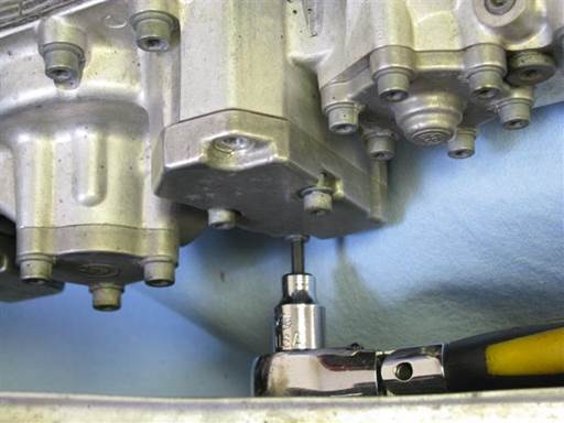
Remove vanos intake solenoid cover.
Remove 4 mounting bolts (4mm hex bit socket 3/8″ / 3/8″ ratchet).
Remove cover. Remove cover paper gasket.
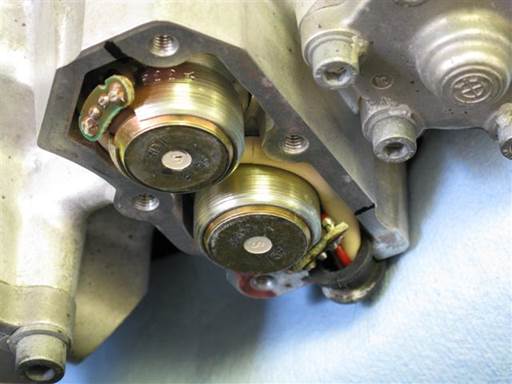
Mark positions of intake solenoids in vanos body.
Mark edge position of each solenoid circuit board on vanos body (marker).
Note: Marks are used to remount solenoids in their original rotational position.
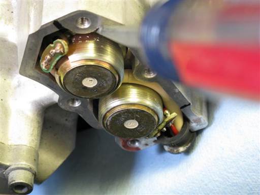
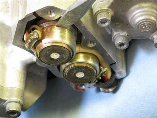
Pry upper intake solenoid out of vanos body.
Leverage against vanos body and pry out solenoid from mid body groove (medium head flathead).
Attempts from multiple positions might be needed to remove solenoid.
Note: Do not leverage against solenoid circuit board as it can be damaged.
Note: Take care to not damage solenoid wires. Press in wires before leveraging on groove adjacent to wires.
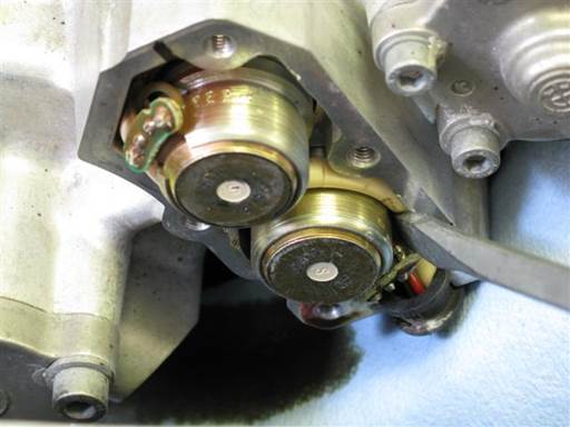
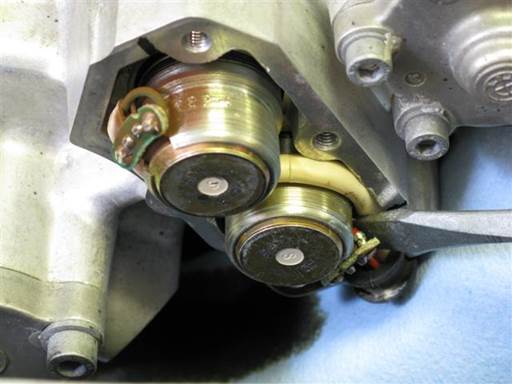
Pry lower intake solenoid out of vanos body.
Leverage against vanos body and pry out solenoid from mid body groove (medium head flathead).
Attempts from multiple positions might be needed to remove solenoid.
Note: Do not leverage against solenoid circuit board as it can be damaged.
Note: Take care to not damage solenoid wires. Press in wires before leveraging on groove adjacent to wires.
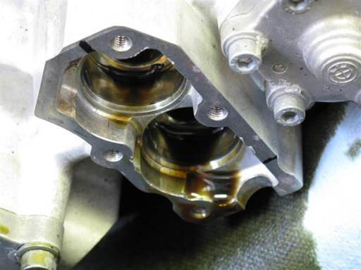
Remove intake solenoids from vanos.
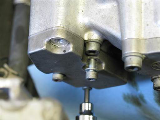
Remove vanos exhaust solenoid cover.
Remove 4 mounting bolts (4mm hex bit socket 3/8″ / 3/8″ ratchet).
Remove cover. Remove cover paper gasket.
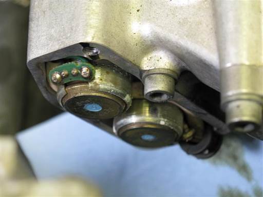
Mark positions of exhaust solenoids in vanos body.
Mark edge position of each solenoid circuit board on vanos body (marker).
Note: Lower solenoid mark is at bottom left edge. See picture below.
Note: Marks are used to remount solenoids in their original rotational position.
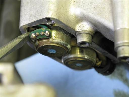
Pry upper exhaust solenoid out of vanos body.
Leverage against vanos body and pry out solenoid from mid body groove (medium head flathead).
Attempts from multiple positions might be needed to remove solenoid.
Note: Do not leverage against solenoid circuit board as it can be damaged.
Note: Take care to not damage solenoid wires. Press in wires before leveraging on groove adjacent to wires.
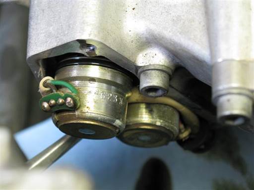
Pry lower exhaust solenoid out of vanos body.
Leverage against vanos body and pry out solenoid from mid body groove (medium head flathead).
Attempts from multiple positions might be needed to remove solenoid.
Note: Do not leverage against solenoid circuit board as it can be damaged.
Note: Take care to not damage solenoid wires. Press in wires before leveraging on groove adjacent to wires.
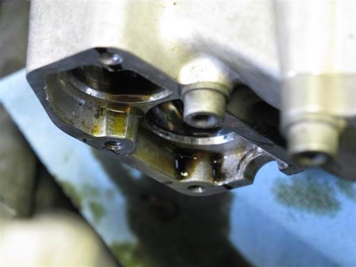
Remove exhaust solenoids from vanos.
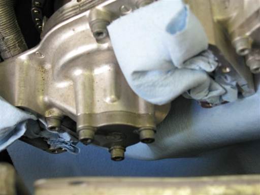
Insert towels in vanos intake and exhaust solenoid chambers to protect oil passages from debris contamination (towels).
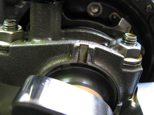
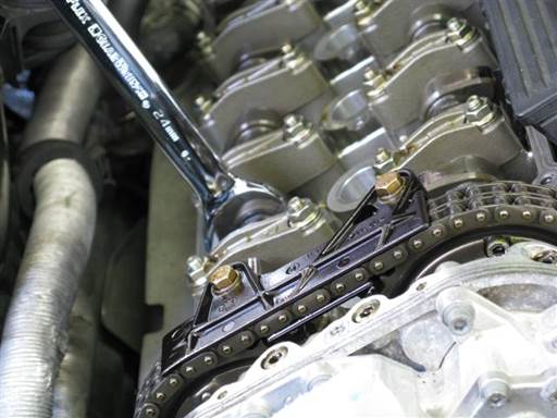
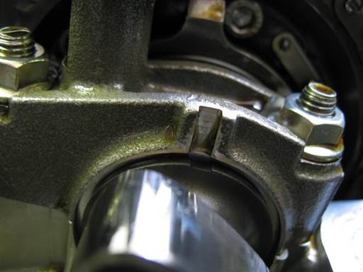
Fully retard exhaust camshaft timing.
Place open wrench (24mm combo wrench) on exhaust camshaft hex at front of camshaft.
Rotate exhaust camshaft counter clockwise to adjustment end position. If camshaft resistant to rotation rock camshaft back and forth to release seize.
Note: Rotating camshaft is most effective when standing at exhaust side of car.
Camshaft groove on first guide bearing will be roughly aligned with groove on first bearing cover (picture).
Note: Camshaft adjustment causes full camshaft timing retard. This causes splined shaft and vanos piston forward positioning. This facilitates access for disconnecting splined shaft from vanos piston in coming step.
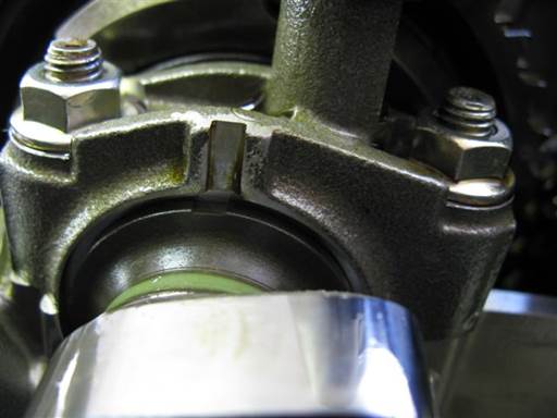
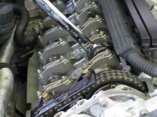
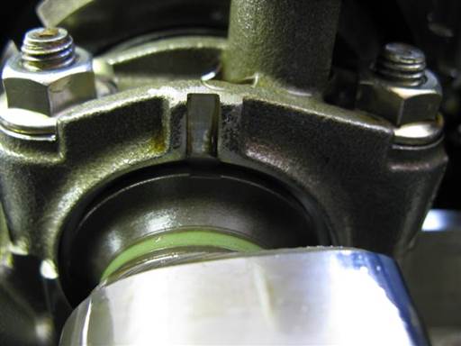
Fully retard intake camshaft timing.
Place open wrench (24mm combo wrench) on intake camshaft hex at front of camshaft.
Rotate intake camshaft counter clockwise to adjustment end position. If camshaft resistant to rotation rock camshaft back and forth to release seize.
Note: Rotating camshaft is most effective when standing at exhaust side of car.
Camshaft groove on first guide bearing will be roughly aligned with groove on first bearing cover (picture).
Note: Camshaft adjustment causes full camshaft timing retard. This causes splined shaft and vanos piston forward positioning. This facilitates access for disconnecting splined shaft from vanos piston in coming step.
Perform rattle procedure
If performing rattle repair continue at this point with rattle procedure, Euro S50 Double Vanos Rattle Procedure
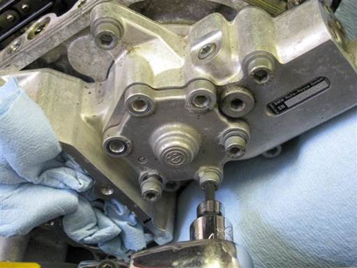
Remove vanos intake cylinder cover bolts.
Remove cover 6 mounting bolts (4mm hex bit socket 3/8″ / 3/8″ ratchet).
Note: If bolt not removed previously, paint drop will be found at bolt head base and cover. This is used in car assembly to verify bolt is fully tightened with toque wrench.
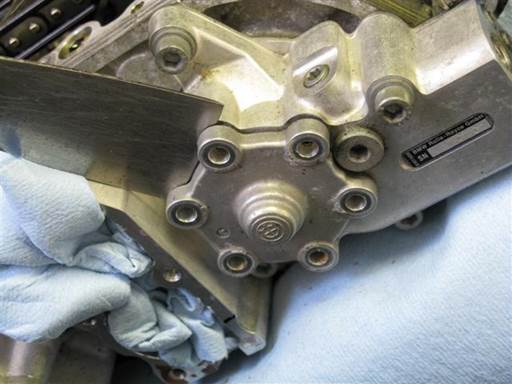
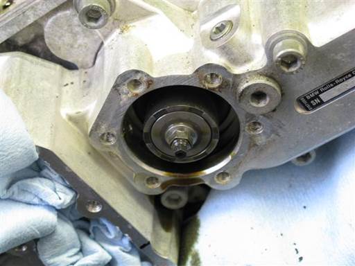
Remove intake cylinder cover.
Pry cover at multiple locations to remove cover evenly (small putty-knife).
Note: Orient blade with edge ramp side to vanos body. This orientation is more effective.
Note: Cover resistance is due to cover sealing O-ring.
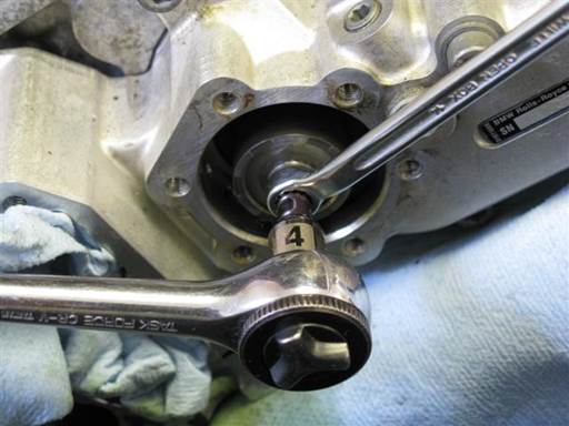
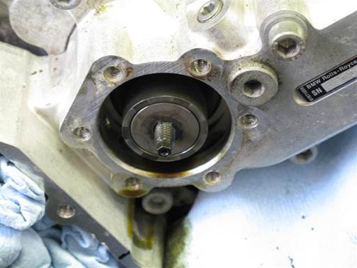
Remove vanos intake piston mounting nut.
Initially loosen nut by counter holding splined shaft stud and unscrewing nut (7mm box wrench, 4mm socket (6-point) 1/4″ / 1/4″ ratchet).
Once nut is loosened, unscrew nut by counter holding nut and screwing splined shaft stud (7mm box wrench, 4mm socket (6 point) 1/4″ / 1/4″ ratchet).
When nut is close to end of shaft and shaft can no longer be held with tool, counter hold piston/shaft by hand and unscrew nut (fingers, 7mm box wrench).
Note: It is critical 6-point socket be used, as 12-point socket is susceptible to stripping shaft hex.
Note: Be sure to use wrench box end, as open wrench is susceptible stripping nut hex.
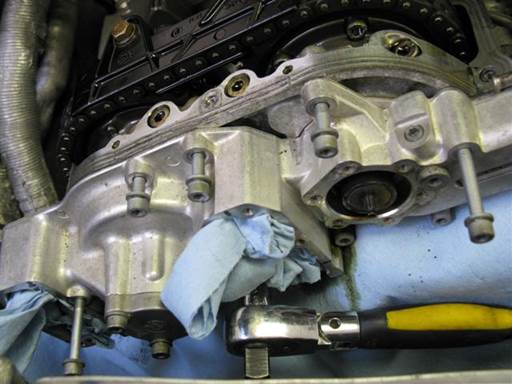
Remove vanos 9 mounting bolts; 5 upper and 4 lower (5mm hex bit socket 3/8″ / 3/8″ ratchet).
Note: Upper right and left end bolts are long. Right bolt is fully threaded and left bolt is partially threaded.
Note: Lower second bolt from right also mounts vanos ground wire.
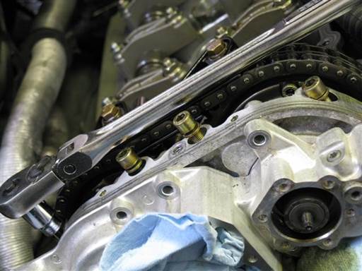
Remove vanos bridge bolts.
Remove vanos bridge 4 mounting bolts (6mm hex bit socket 3/8″ / 3/8″ long-arm ratchet).
Note: Center 2 bolts are long and outer 2 bolts are short.
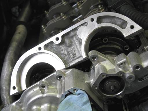
Remove vanos bridge.
Wiggle vanos bridge while pulling up to remove vanos bridge from engine head.
Note: Gasket sealant at base of bridge acts as adhesive mounting bridge to engine head. Wiggling bridge helps break sealant bond.
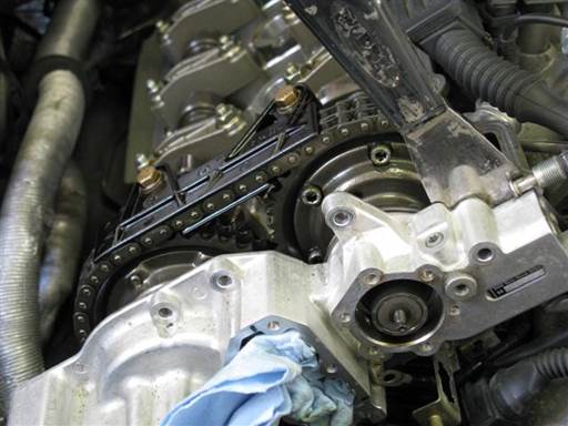
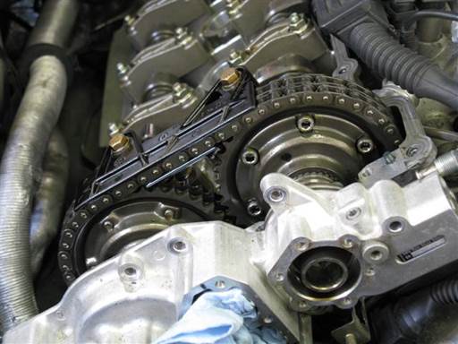
Pry vanos forward off engine head.
Pry between vanos and engine head at vanos top right and left ends (medium putty-knife).
Pry vanos evenly rotating between each side until vanos releases and separates from engine head.
Note: Vanos resistance is due to vanos intake and exhaust head sealing O-rings.
Pull vanos forward as far as possible.
Note: Once vanos comes off engine head, vanos will be suspended on intake and exhaust splined shafts.
Caution: Once vanos is pulled off engine head it should not be remounted without aligning exhaust side vanos oil pump and camshaft oil pump driver. A misalignment combined with pressure from vanos mounting bolts will cause breakage of vanos bridge.
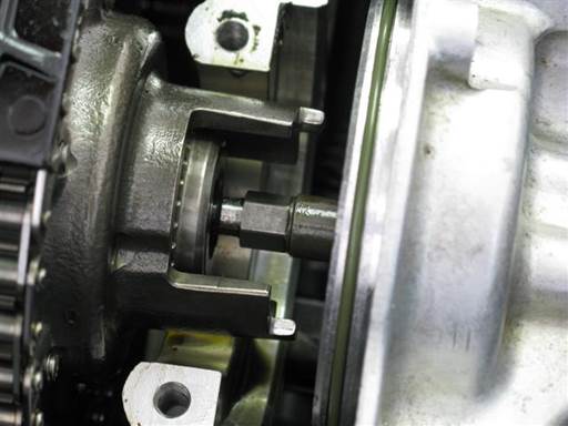
Reposition exhaust camshaft if necessary.
Exhaust sprocket hub can be in a position with an oil pump driver tower up.
If this occurs and precludes access to splined shaft stud and vanos exhaust piston for disconnection, turn crankshaft clockwise to position exhaust hub for better work access (picture) (crankshaft turning socket / 1/2″ long-arm ratchet).
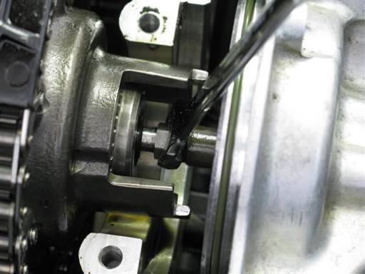
Disconnect vanos exhaust piston from exhaust splined shaft stud.
Rotate vanos exhaust piston to allow tool access to splined shaft stud flats (10mm open wrench).
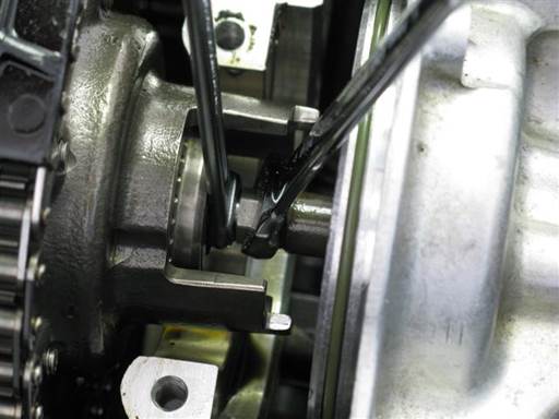
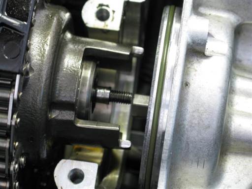
Disconnect vanos exhaust piston from exhaust splined shaft stud.
Counter hold splined shaft stud and unscrew vanos exhaust piston; left hand thread (7mm open wrench, 10mm open wrench).
Note: Piston and shaft stud are left hand thread, thus unscrew by turning piston tool (10mm open wrench) from left to right (clockwise) (car front orientation).
Note: Rotate piston tool (10mm open wrench) at every turn to facilitate tool access.
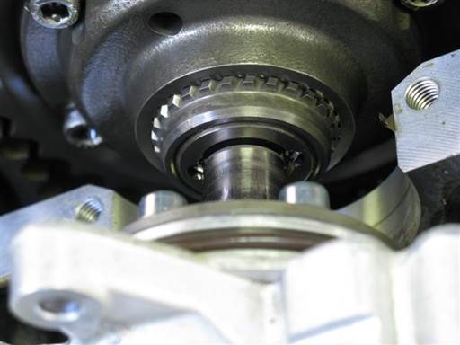
Remove vanos from engine head by removing vanos intake piston from intake splined shaft stud.
Lift up vanos. Wiggle and pull forward on vanos to remove vanos intake piston from intake splined shaft stud.
Note: Splined shaft stud inserted in piston has O-ring at center which mates with piston inner diameter. Resistance to removal is due to this O-ring.
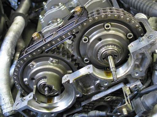
Take vanos to work bench.
Clean outside of vanos to remove dirt and sludge (brake cleaner & towels).
Installation of vanos seals
During following seals installation procedure, great care should be taken to not drop and damage vanos components. Perform work over table, so if part is dropped it will fall to table top.
Note: Try to not disturb vanos oil pump rotational position. Oil pump is currently aligned to mate with exhaust camshaft oil pump driver.
Installation of vanos intake seals
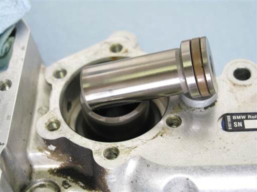
Remove intake piston from intake cylinder.
Press piston from vanos inboard side to remove piston from vanos outboard side (finger).
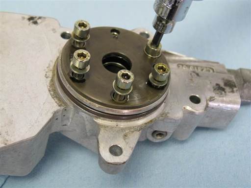
Remove intake cylinder cover from vanos inboard side.
Remove 5 mounting bolts (4mm hex bit socket 3/8″ / 3/8″ ratchet).
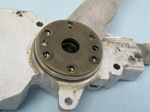
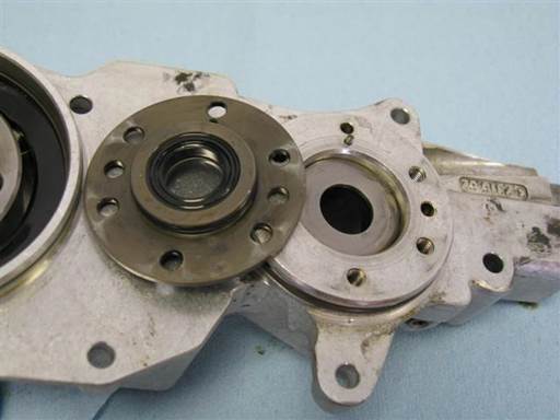
Remove intake cylinder cover.
Pry cover at multiple locations to evenly remove cover (small putty-knife).
Note: Orient blade with edge ramp side to vanos body. This orientation is more effective.
Note: Cover resistance is due to cover sealing O-ring.
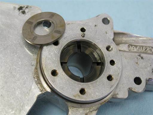
Remove intake cover washer (fingers).
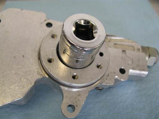
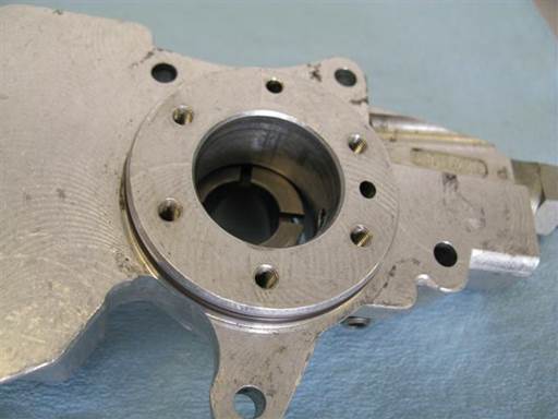
Remove intake cylinder form vanos housing.
Press intake cylinder from vanos inboard side to remove it from vanos outboard side. (24mm 1/2″ socket).
If cylinder resistant, hit press tool to knock out cylinder (1/2″ ratchet head side).
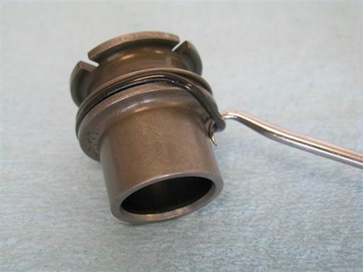
Remove intake cylinder sealing O-ring.
Pry O-ring from cylinder groove and remove from cylinder (hook pick).
Clean intake cylinder (brake cleaner & towels).
Clean intake cylinder vanos housing (brake cleaner & towels).
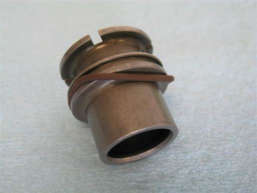
Install new O-ring on intake cylinder.
Insert new O-ring in cylinder groove on one end and stretch other end over cylinder and drop into groove (fingers).
Lightly lubricate O-ring to ease cylinder installation (assembly oil).
Note: Intake cylinder O-ring is one of three identical O-rings. Other identical O-rings are intake inboard cover O-ring and exhaust outboard cover O-ring.
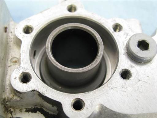
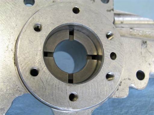
Lightly lubricate intake cylinder vanos housing to ease cylinder installation (assembly oil).
Insert intake cylinder into vanos housing from vanos outboard side.
Rotate cylinder in vanos to align cylinder cutouts with vanos housing oil access holes at sides of vanos cylinder housing.
Turn vanos inboard side down to keep cylinder in housing.
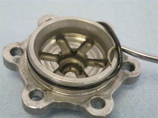
Remove intake cylinder outboard cover sealing O-ring.
Pry O-ring from cover groove and remove from cover (hook pick).
Clean intake cylinder cover (brake cleaner & towels).
Note: Do not install new cover O-ring at this time. Cover will be easier to install and remove in next step without cover O-ring.
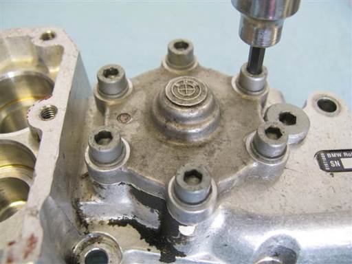
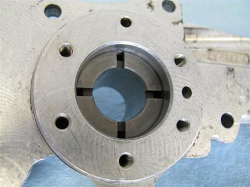
Install and then remove intake cylinder outboard cover.
Align cover bolt holes to vanos body bolts holes.
Install cover 6 mounting bolts (4mm hex bit socket 3/8″).
Tighten bolts evenly in multiple passes.
Note: Tightening cover bolts presses intake cylinder into vanos housing.
Remove cover 6 mounting bolts (4mm hex bit socket 3/8″).
Remove cylinder cover.
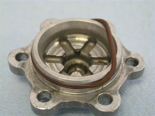
Install new O-ring on intake cylinder cover.
Insert new O-ring in cover groove on one end and stretch other end over cover and drop into groove (fingers).
Lightly lubricate O-ring to ease cover installation (assembly oil).
Note: Intake cylinder cover O-ring is larger than two other similar in size O-rings.
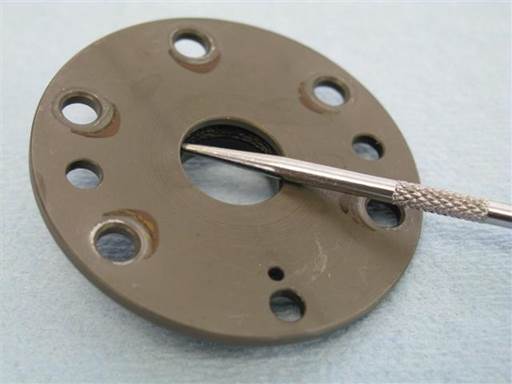
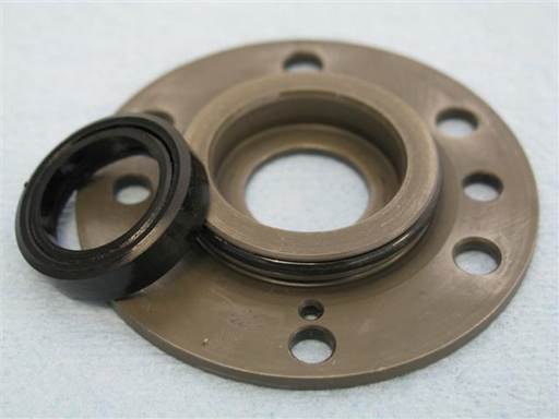
Remove intake rod seal from intake inboard cylinder cover.
Pry rod seal from cover outboard side to remove it from cover inboard side (strait pick).
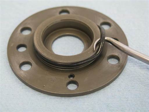
Remove intake cylinder inboard cover sealing O-ring.
Pry O-ring from cover groove and remove from cover (hook pick).
Clean intake cylinder inboard cover (brake cleaner & towels).
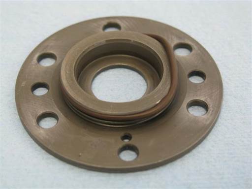
Install new O-ring on intake cylinder inboard cover.
Insert O-ring in cover groove on one end and stretch other end over cover and drop into groove (fingers).
Lightly lubricate O-ring to ease cover installation (assembly oil).
Note: Intake cylinder inboard cover O-ring is one of two remaining identical O-rings. Other identical O-ring is exhaust outboard cover O-ring.
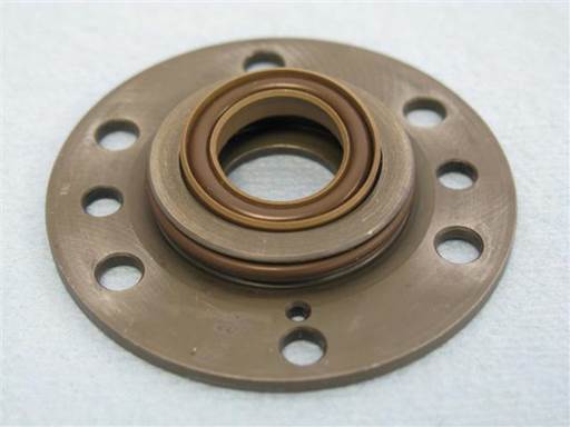
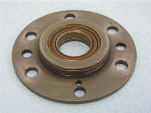
Install new intake rod seal into intake cylinder inboard cover.
Insert seal into housing on one side and press seal into housing on opposite side.
Once seal inserts into housing, press seal fully into housing along its perimeter (thumb).
Seal should fully insert into housing (picture).
Press O-ring into rod seal to verify O-ring full insertion.
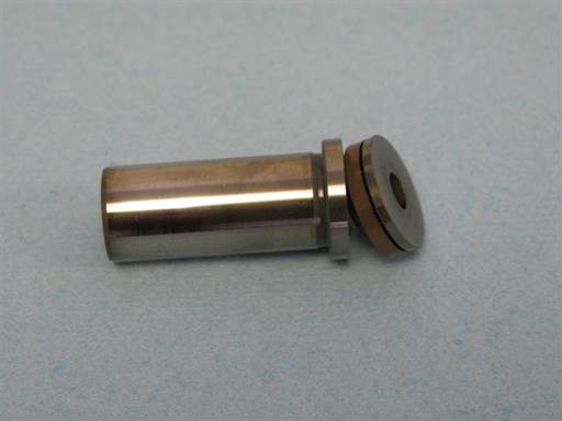
Disconnect intake piston end cap from main piston body (hands).
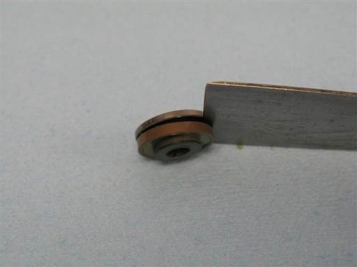
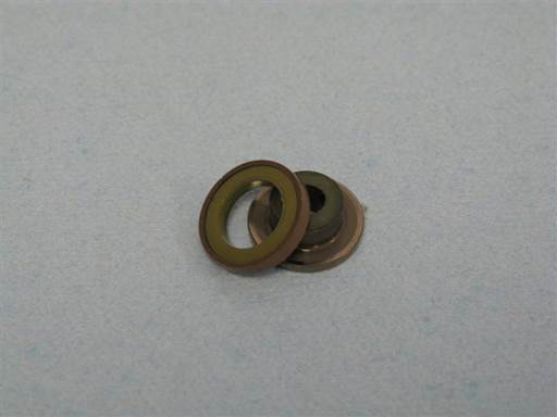
Remove intake piston seal from intake piston cap.
Pry piston seal from piston cap (small putty-knife).
Note: Orient putty-knife with edge ramp side to piston cap wall. This orientation is more effective.
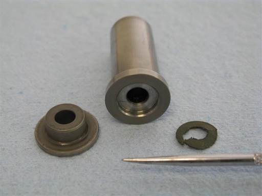
Remove paper gasket from intake piston or piston cap.
Pry off and scrape off paper gasket as necessary from piston or piston cap (strait pick).
Fully remove all paper gasket.
Note: Paper gasket excessively widens piston seal groove allowing seal to tilt in groove and wear unevenly. Gasket only seems to function to better seat piston cap before mounting. This is not needed.
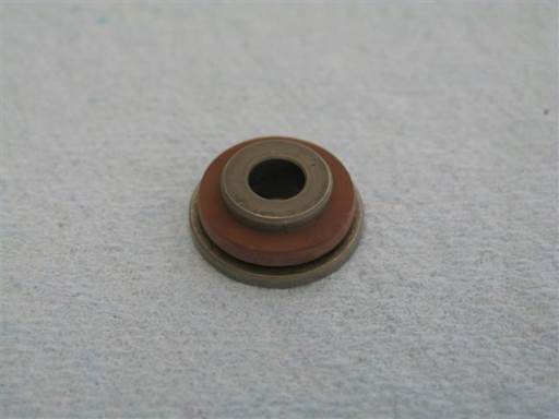
Install new piston seal rubber ring on piston cap shaft (fingers).
Fully insert rubber ring onto piston cap (fingers).
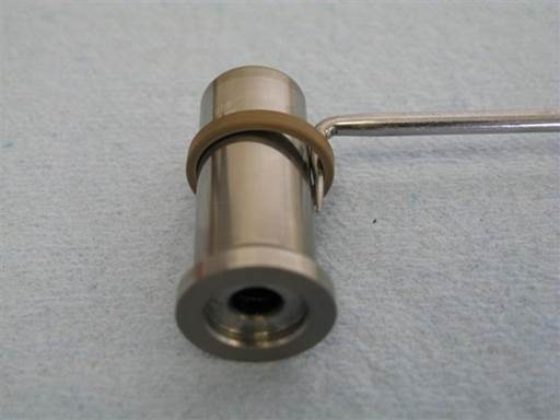
Stretch intake piston new Teflon ring.
Place Teflon ring on piston shaft and pick tool on Teflon ring (90 degree pick) (picture).
Leverage pick tool against piston and tilt pick tool to stretch out Teflon ring (90 degree pick).
Perform Teflon ring stretching at multiple locations along Teflon ring until Teflon ring notably stretches.
Note: Teflon ring needs to stretch sufficiently to install over piston seal rubber ring in next step.
Note: Multiple attempts can be made of stretching Teflon ring and attempting next step install.
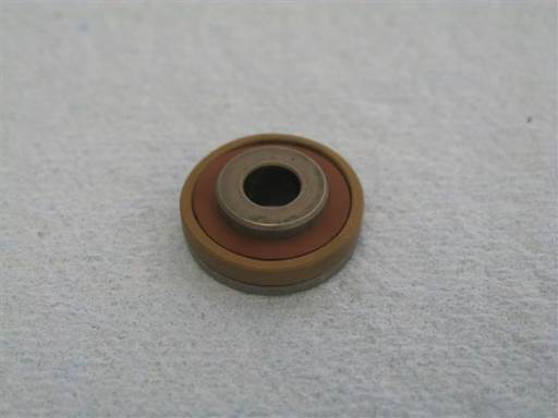
Install piston seal Teflon ring onto piston seal rubber ring.
If Teflon ring is too small, repeat previous Teflon ring stretching step.
Continue stretching and attempting to install Teflon ring until it installs.
Do not over stretch Teflon ring. Stretch only sufficiently to install.
Fully insert Teflon ring onto rubber ring.
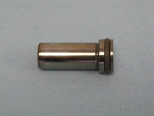
Mount intake piston cap onto intake piston.
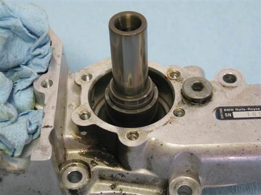
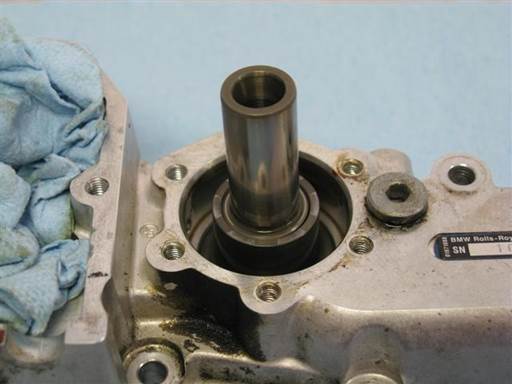
Insert intake piston seal end into intake cylinder outboard side.
Lightly lubricate cylinder entry inner wall and piston Teflon ring (assembly oil).
Wiggle piston and press strait into cylinder.
Verify Teflon ring is inserting into cylinder at all perimeter locations. Reposition piston and reattempt insertion to facilitate Teflon ring full perimeter insertion.
Once all Teflon ring perimeter inserts into cylinder, wiggle piston and press strait into cylinder to fully insert Teflon ring into cylinder.
Note: Cylinder entry has chamfer which allows for stretched Teflon ring to be collected and inserted into cylinder.
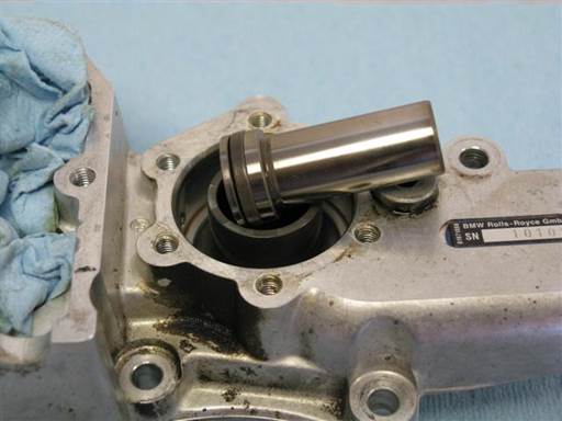
Maintain piston in cylinder for 1 minute then remove.
This period allows Teflon ring to be compressed (resized) close to original size.
Remove piston from cylinder.
Note Teflon ring has decreased in diameter.
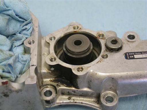
Remove piston cap from piston.
Place piston cap, shaft first, into intake cylinder outboard end.
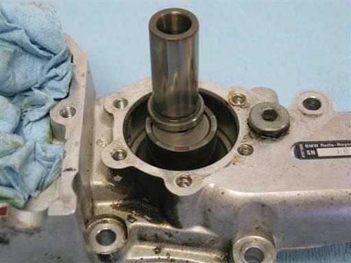
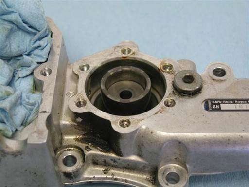
Insert piston cap into cylinder by pressing with piston cap end.
Press cap ~1/3 down cylinder.
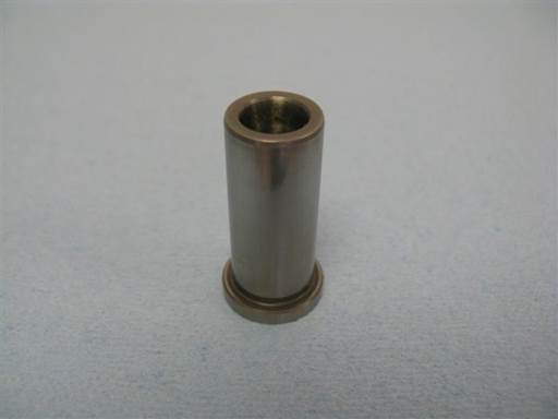
Place intake piston vertically with cap end down.
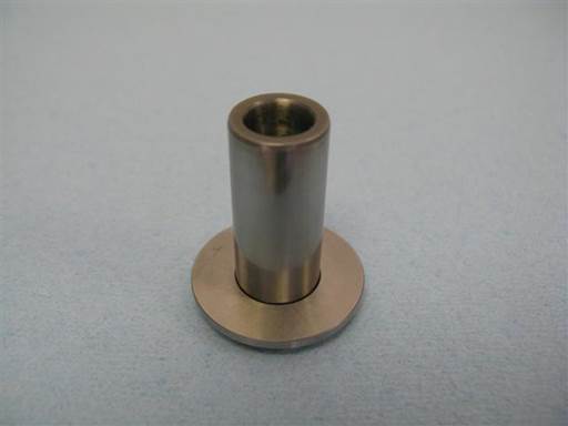
Slide intake cylinder cover washer onto piston.
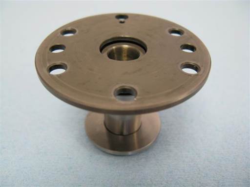
Insert intake cylinder cover with new rod seal onto piston.
Lightly lubricate piston and rod seal inner Teflon lip (assembly oil).
Press cover strait onto piston without tilting.
Press cover over piston until ~10mm of piston is protruding from cover (next picture).
Clean vanos intake cylinder inboard side cover mating surfaces and cover mounting bolts (brake cleaner & towels).
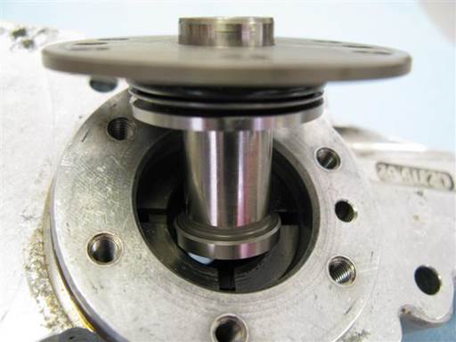
Insert intake piston, cap end first, into intake cylinder inboard side.
Slide cylinder cover washer up to cover.
Insert piston into cylinder.
Mount piston to piston cap by pressing on piston and piston cap from both ends of cylinder (finger, hand).
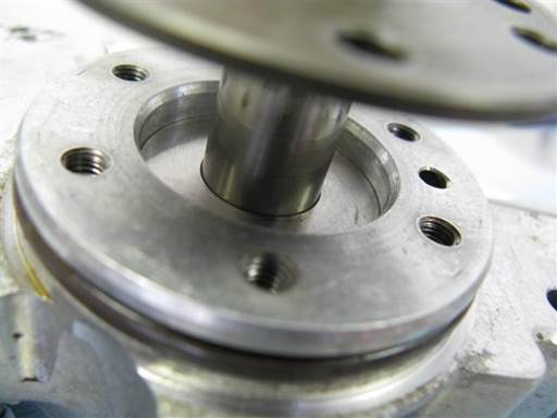
Mount intake cylinder cover washer onto cylinder.
Fully seat washer.
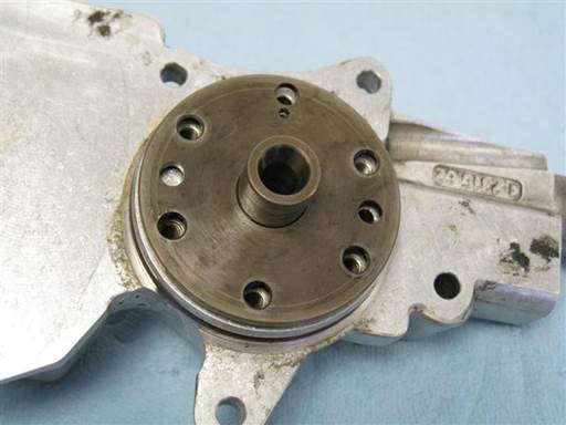
Mount intake cylinder cover onto vanos body.
Rotate cover/piston to align cover holes with vanos body holes (picture).
Brace piston from vanos outboard side (finger) and press cover down piston and onto vanos body.
Rotate cover/piston to align cover holes with vanos body holes (picture).
Press cover onto vanos body.
If present, cover alignment small pin hole will insert onto vanos body alignment pin.
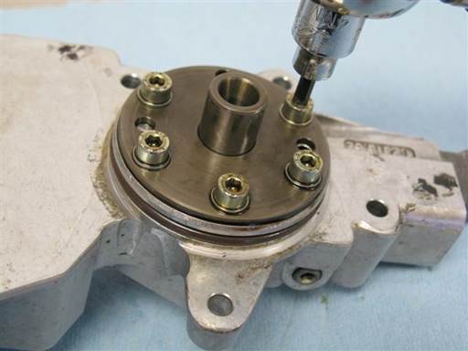
Install intake cover 5 mounting bolts (4mm hex bit socket 3/8″ / 3/8″ ratchet).
Tighten bolts evenly to draw cover evenly to vanos body.
Note: If top end of cover not inserting hit with object to insert (ratchet handle)
Fully tighten, 6 Nm (4.5 ft-lb) (4mm hex bit socket 3/8″ / 3/8″ torque wrench).
Note: Tighten bolts evenly in multiple passes. Verify one pass with all bolts fully tightened.
Installation of vanos exhaust seals
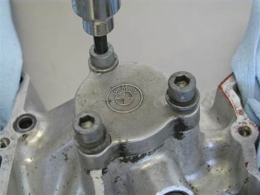
Remove vanos exhaust cylinder cover from vanos outboard side.
Remove cover 3 mounting bolts (5mm hex bit socket 3/8″ / 3/8″ ratchet).
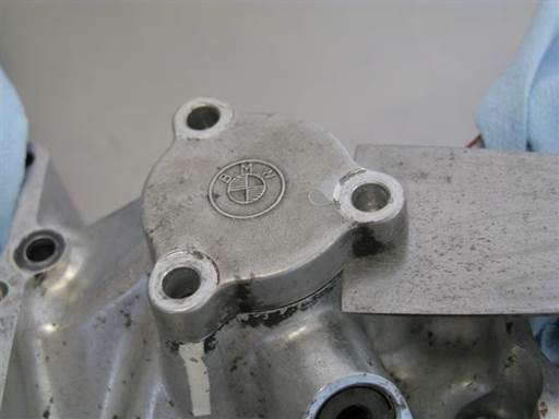
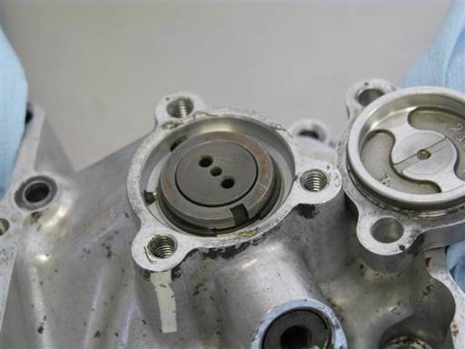
Remove exhaust cylinder cover.
Pry cover at multiple locations to evenly remove cover (small putty-knife).
Note: Orient blade with edge ramp side to vanos body. This orientation is more effective.
Note: Cover resistance is due to cover sealing O-ring.
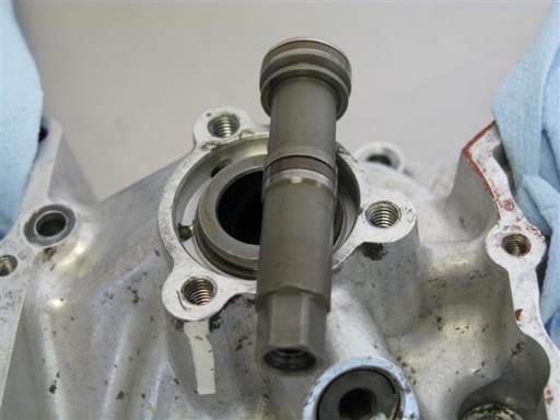
Remove exhaust piston from exhaust cylinder.
Press piston from vanos inboard side to remove piston from vanos outboard side (finger).
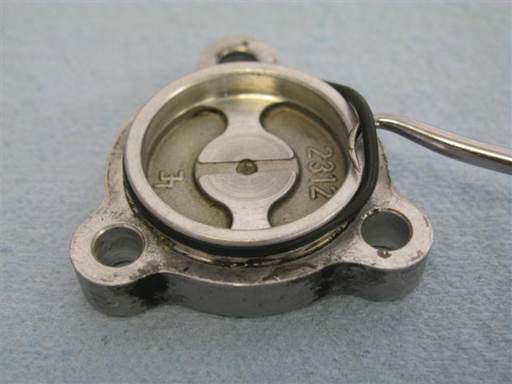
Remove exhaust cylinder cover sealing O-ring.
Pry O-ring from cover groove and remove from cover (hook pick).
Clean exhaust cylinder cover (brake cleaner & towels).
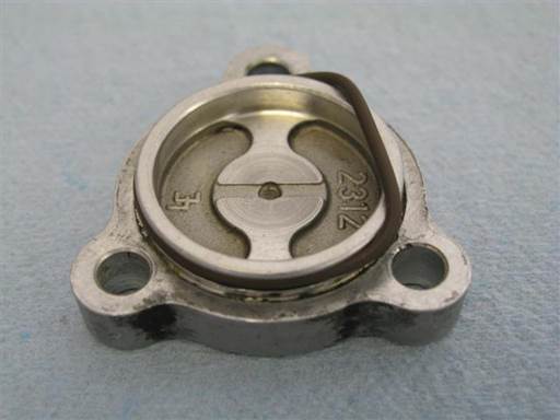
Install new O-ring on exhaust cylinder cover.
Insert O-ring in cover groove on one end and stretch other end over cover and drop into groove (fingers).
Lightly lubricate O-ring to ease cover installation (assembly oil).
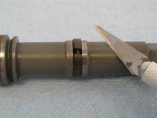
Cut cross section of exhaust piston middle seal Teflon ring (razor knife).
Note: Rocking of blade while pressing helps create cutting motion.
Rotate blade in seal after cutting to note any remaining uncut seal (razor knife).
Remove cut Teflon ring from piston grove.
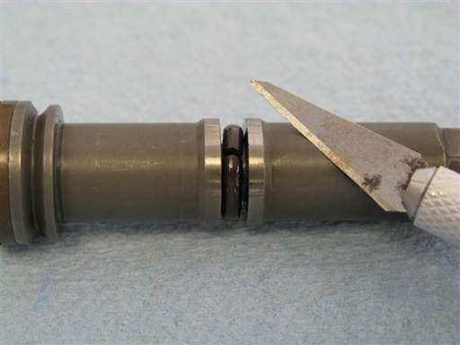
Cut cross section of exhaust piston middle seal O-ring (razor knife).
Note: Rocking of blade while pressing helps create cutting motion.
Rotate blade in seal after cutting to note any remaining uncut seal (razor knife).
Remove cut O-ring from piston grove.
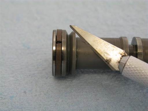
Cut cross section of exhaust piston end seal Teflon ring (razor knife).
Note: Rocking of blade while pressing helps create cutting motion.
Rotate blade in seal after cutting to note any remaining uncut seal (razor knife).
Remove cut Teflon ring from piston grove.
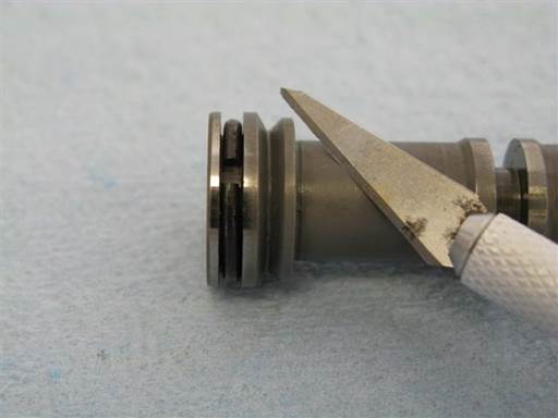
Cut cross section of exhaust piston end seal O-ring (razor knife).
Note: Rocking of blade while pressing helps create cutting motion.
Rotate blade in seal after cutting to note any remaining uncut seal (razor knife).
Remove cut O-ring from piston grove.
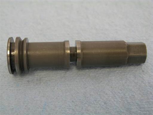
When seals removal is complete, piston seal grooves will have exposed metal with no seals.
Clean exhaust piston (brake cleaner & towels).
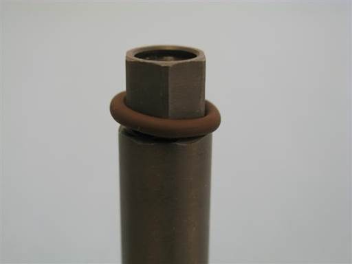
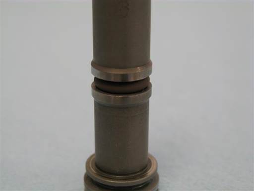
Mount exhaust piston middle seal O-ring onto exhaust piston small end and roll O-ring along piston and drop into seal groove (fingers).
Center O-ring in seal groove (strait pick).
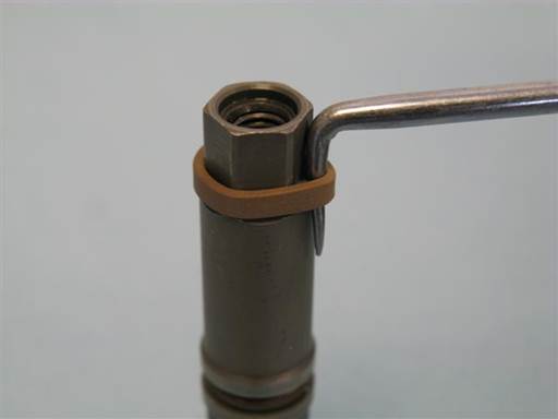
Mount exhaust piston middle seal Teflon ring onto exhaust piston small end.
Insert pick tool between Teflon ring and piston (90 degree pick) (picture).
Leverage pick tool against piston and tilt pick tool to stretch out Teflon ring (90 degree pick).
Perform Teflon ring stretching at multiple locations along Teflon ring until Teflon ring notably stretches.
Note: Teflon ring needs to stretch sufficiently to slide over piston larger diameter.
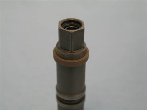
Place exhaust piston vertically with large end down.
Press down on Teflon ring from top end to press Teflon ring onto piston larger diameter (fingers/nails).
Move Teflon ring evenly along piston (picture).
Note: If Teflon ring difficult to press down repeat previous Teflon ring stretching step.
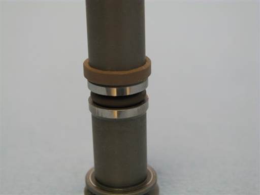
Slide Teflon ring down exhaust piston to seal groove rim (fingers/nails) (picture).
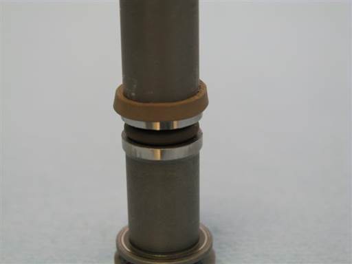
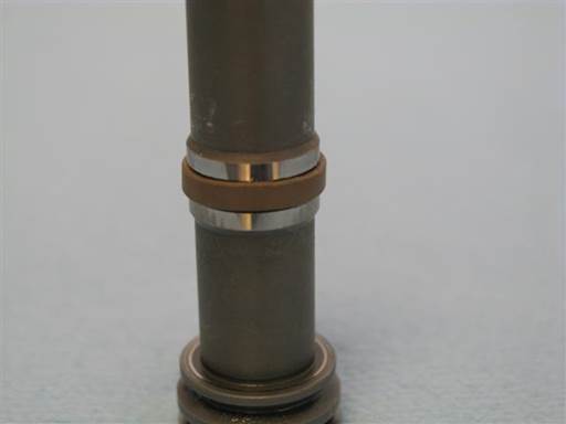
Press down on Teflon ring from top end to press Teflon ring onto piston seal groove rim and drop Teflon ring into seal groove (fingers/nails).
Move Teflon ring evenly along piston (picture).
Note: It has been found that it is practical to first compress this small Teflon ring as next step and insert it into the exhaust cylinder for a few minutes, as shown a few steps below.
After that continue here with the ring on the piston bottom.
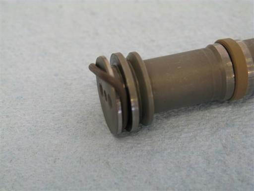
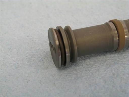
Insert exhaust piston end seal O-ring in piston seal groove at one end and stretch other end over piston and drop into seal groove (fingers).
Center O-ring in seal groove (strait pick).
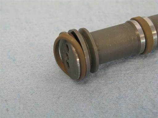
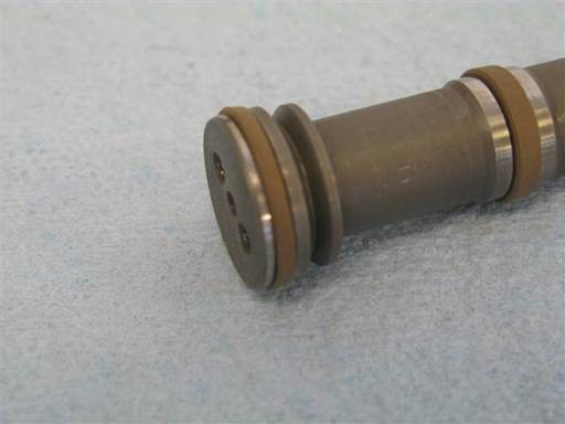
Insert exhaust piston end seal Teflon ring in piston seal groove at one end and stretch other end over piston and drop into seal groove (fingers).
Stretch Teflon ring at multiple location along Teflon ring before final stretch over piston and into groove (fingers).
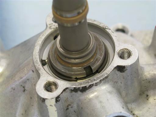
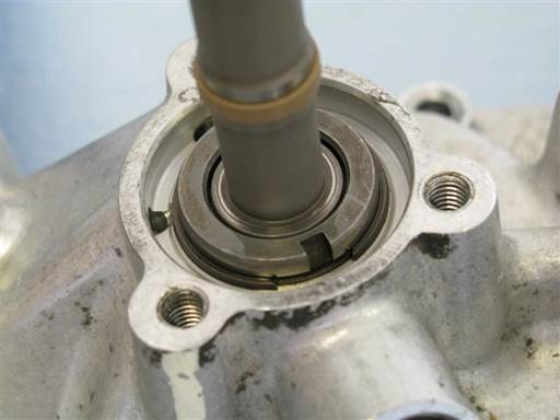
Insert exhaust piston large end into exhaust cylinder outboard side.
Lightly lubricate cylinder entry inner wall and piston Teflon ring (assembly oil).
Wiggle piston and press strait into cylinder.
Verify Teflon ring is inserting into cylinder at all perimeter locations. Reposition piston and reattempt insertion to facilitate Teflon ring full perimeter insertion.
Once all Teflon ring perimeter inserts into cylinder, wiggle piston and press strait into cylinder to fully insert Teflon ring into cylinder.
Note: Cylinder entry has chamfer which allows for stretched Teflon ring to be collected and inserted into cylinder.
Caution: Once Teflon ring fully inserts into cylinder do not further insert piston into cylinder. There is a groove at cylinder middle that will entrap piston seal and piston will then be very difficult to remove.
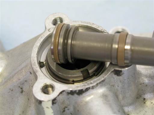
Maintain piston in cylinder for 1 minute then remove.
This period allows Teflon ring to be compressed (resized) close to original size.
Remove piston from cylinder.
Note Teflon ring has decreased in diameter.
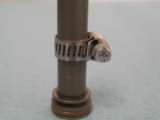
Place small hose clamp around exhaust piston middle seal Teflon ring (small hose clamp).
Tighten clamp until it seats on piston (Philips).
Note: Only lightly tighten clamp on piston.
Note: Mounting clamp on piston middle seal Teflon ring will compress Teflon ring to close to original size and allow piston insertion in next step.
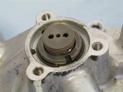
Remove hose clamp from exhaust piston (Philips).
Note Teflon ring has compressed.
Note: Clamp will leave slight crease on Teflon surface. This crease will rectify once Teflon ring is heated in engine.
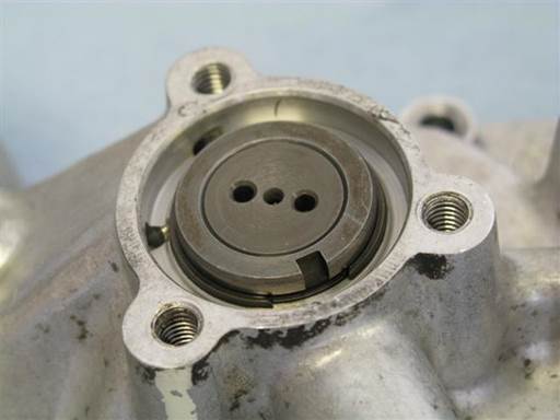
Lightly lubricate exhaust piston middle seal Teflon ring (assembly oil).
Insert exhaust piston small end into exhaust cylinder outboard side.

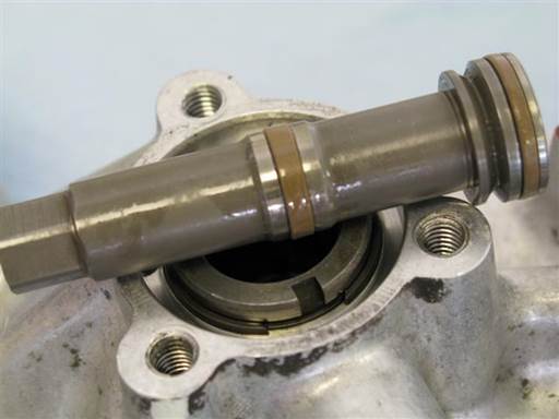
Place flat object on exhaust piston end (small putty-knife handle).
Press down on piston with moderate pressure until piston inserts into cylinder (picture).
Note: During this step Piston middle seal Teflon ring is being inserted into exhaust smaller cylinder. Cylinder entry has chamfer which will allow for stretched Teflon ring to be collected and inserted into cylinder.
Maintain piston in cylinder for 1 minute then remove.
This period allows Teflon ring to be compressed (resized) close to original size.
Remove piston from cylinder by pressing piston from inboard side.
Note Teflon ring has decreased in diameter.
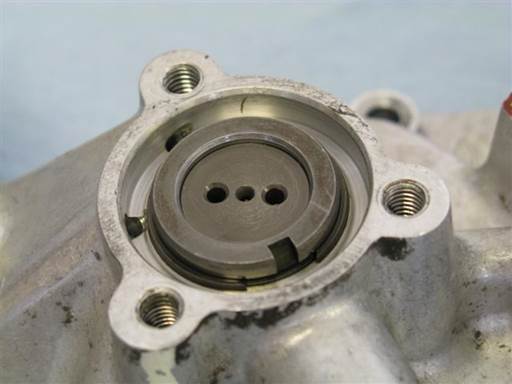
Insert exhaust piston small end first into exhaust cylinder outboard side and press piston into cylinder.
Clean vanos exhaust cylinder outboard side cover mating surfaces and cover mounting bolts (brake cleaner & towels).
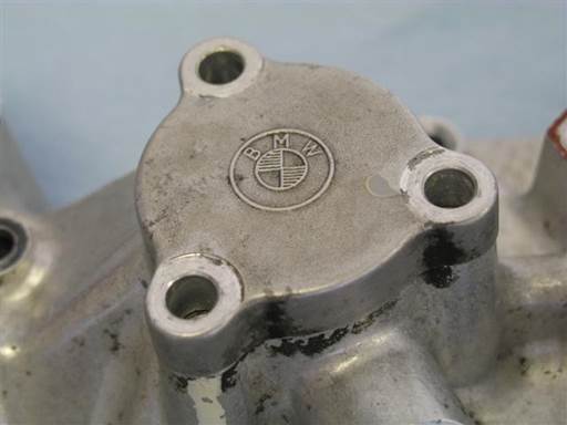
Install exhaust cylinder cover on vanos.
Orient cover so that BMW insignia can be read (picture) (this presumes vanos intake side on right).
Align cover bolt holes to vanos body bolts holes.
Press cover onto vanos body.

Install exhaust cover 3 mounting bolts (5mm hex bit socket 3/8″ / 3/8″ ratchet).
Tighten bolts evenly to draw cover evenly to vanos body.
Fully tighten, 10 Nm (7 ft-lb) (5mm hex bit socket 3/8″ / 3/8″ torque wrench).
Note: Tighten bolts evenly in multiple passes. Verify one pass with all bolts fully tightened.

Remove vanos inboard intake head sealing O-ring.
Pry O-ring from housing groove and remove from vanos (hook pick).
Clean O-ring housing groove (brake cleaner & towels).

Install new O-ring on vanos inboard intake head sealing housing.
Insert new O-ring in housing groove on one end and stretch other end over housing and drop into groove (fingers).
Lightly lubricate O-ring to ease vanos installation (assembly oil).

Remove vanos inboard exhaust head sealing O-ring.
Pry O-ring from housing groove and remove from vanos (hook pick).
Clean O-ring housing groove (brake cleaner & towels).

Install new O-ring on vanos inboard exhaust head sealing housing.
Insert new O-ring in housing groove on one end and stretch other end over housing and drop into groove (fingers).
Lightly lubricate O-ring to ease vanos installation (assembly oil).

Remove vanos inboard oil feed head sealing O-ring.
Pry O-ring from face groove and remove from vanos (hook pick).
Clean O-ring face groove (brake cleaner & towels).

Install new O-ring on vanos inboard oil feed head sealing face.
Insert new O-ring in face groove (fingers).
Note: Oil feed O-ring is similar in size to oil pressure restrictor small O-ring. Oil feed O-ring is slightly thicker in cross section than oil pressure restrictor small O-ring.

Unscrew oil pressure restrictor from vanos body (hand).
Drain and discard oil from vanos.
Clean restrictor and vanos restrictor area (brake cleaner & towels).

Cut cross section of small O-ring on pressure restrictor (razor knife).
Note: Rocking of blade while pressing helps create cutting motion.
Note: Take care to not cut or damage adjacent plastic washer. Plastic washer has cut cross section.
Remove cut O-ring from pressure restrictor.

Remove large O-ring from pressure restrictor (90 degree pick).
Clean pressure restrictor O-ring grooves (brake cleaner & towels).

Install new large O-ring on pressure restrictor. Roll O-ring onto pressure restrictor until O-ring drops into base groove.
Install small O-ring on pressure restrictor. Roll O-ring onto pressure restrictor until O-ring drops into groove.
Note: White washer should be positioned in groove on side of regulator large end (picture).
Lightly lubricate O-rings to ease pressure restrictor installation (assembly oil).

Screw pressure restrictor into vanos body (hand).
Note: Pressure restrictor will be tightened once vanos is mounted on engine.

Remove intake splined shaft stud O-ring.
Pry O-ring from stud groove and remove from stud (90 degree pick).
Clean splined shaft stud (brake cleaner & towels).

Note: If installing rattle kit, delay splined shaft O-ring installation until after rattle kit installation.
Install new O-ring on intake splined shaft stud.
Insert new O-ring on splined shaft stud and roll O-ring down stud and drop into groove (fingers).
Lightly lubricate O-ring to ease vanos installation (assembly oil).
For intake and exhaust solenoid pair, perform following O-rings removal and install.


Cut cross section of solenoid small and large O-rings (razor knife).
Note: Rocking of blade while pressing helps create cutting motion.
Note: Do not press into solenoid as this nicks sealing surface.
Rotate blade in O-ring after cutting to note any remaining uncut O-ring (razor knife).
Remove cut O-rings from solenoid.
Clean solenoid (brake cleaner & towels).

Install new small and large O-rings on solenoid (fingers).
O-rings should not be twisted in final position.

Repeat solenoid O-rings removal and install for second solenoid.
Lightly lubricate O-rings to ease solenoid installation (assembly oil).
Repeat O-rings removal and install for second solenoid pair.


Remove vanos oil filter and washer (5mm hex bit socket 3/8″ / 3/8″ ratchet).
Clean vanos outer face at oil filter hole (brake cleaner & towels).


Install vanos new oil filter and washer (5mm hex bit socket 3/8″ / 3/8″ ratchet).
Fully tighten, 12 Nm (9 ft-lb) (5mm hex bit socket 3/8″ / 3/8″ torque wrench).

Remove towels from vanos solenoid chambers.
Clean vanos solenoid chambers (brake cleaner & towels).
Clean vanos solenoid housing and cover matting surfaces (brake cleaner & towels).
Note: Do not erase solenoid alignments marks.

Insert new clean towels in vanos solenoid chambers to protect oil passages from debris contamination (towels).
Cleaning of parts
Note: When cleaning parts, spray cleaning compound on towel then wipe component with towel. Components can also be placed in small container and sprayed with cleaning compound then individually wiped with towel.
Clean all mounting bolts, nuts, washers (brake cleaner & towels).
Clean vanos matting surfaces; solenoid covers and bolts, intake cylinder housing and cover bolts, inboard face (brake cleaner & towels).
Note: Do not rotate vanos exhaust oil pump.
Clean vanos bridge polished surfaces; top gasket surface, arches, base bottom (remove old sealant) (brake cleaner & towels).
Clean head matting surfaces; sparkplug well, top perimeter and front half-moons, front polished surfaces, exhaust splined shaft stud (brake cleaner & towels).
Clean vanos ground wire and valve cover ground wire (brake cleaner & towels).
Clean coils mounting contact surfaces (at coils) (brake cleaner & towels).
Remove valve cover gaskets from valve cover.
Clean valve cover gaskets (brake & towels). Note: Euro S50 valve cover gaskets are made of Viton and thus can withstand brake cleaner. Brake cleaner will allow for removing oil from gaskets.
Clean valve cover mating surfaces; inner gasket, bolt access holes, all studs (brake cleaner & towels).
Installation of vanos

Slightly advance exhaust camshaft position.
Rotate exhaust camshaft slightly clockwise (24mm open wrench).
Align exhaust timing grooves so camshaft bearing groove is slightly left of bearing cover groove (car rear orientation) (picture). If camshaft resistant to rotation rock camshaft back and forth to release seize.
Note: Rotating camshaft is most effective when standing at exhaust side of car.
Note: This step insures vanos exhaust piston will not bottom out on vanos exhaust cylinder cover and obstruct matting of vanos to cylinder head.

Slightly advance intake camshaft position.
Rotate intake camshaft slightly clockwise (24mm open wrench).
Align intake timing grooves so camshaft bearing groove is slightly left of bearing cover groove (car rear orientation) (picture). If camshaft resistant to rotation rock camshaft back and forth to release seize.
Note: Rotating camshaft is most effective when standing at exhaust side of car.
Note: This step insures vanos intake piston/splined shaft stud do not protrude too far and obstruct mounting of vanos intake cylinder cover.

Inspect TDC (top dead center) timing marks on engine timing cover and crankshaft harmonic balancer at ~11 o”clock position (mirror).
If needed, adjust crankshaft pulley to align TDC timing marks (crankshaft turning socket / 1/2″ long-arm ratchet).
Note: Precise alignment is not necessary.
If crankshaft adjusted, double check and readjust camshafts timing as above.

After above camshafts adjustment, intake and exhaust splined shafts will be slightly more recessed into corresponding sprockets (picture).


Move vanos ground wire forward and position end under vanos solenoid cable connector bracket.
Note: This allows installing vanos on engine head without ground wire being caught between vanos and engine head.

Verify vanos inboard side is clean and ready for installation.
As needed, wipe down vanos inboard surfaces (brake cleaner & towels).
Note: Do not rotate vanos exhaust oil pump.

Install vanos on engine head.
Insert vanos intake piston onto intake splined shaft stud.
Stop when resistance is met.


Insert thumb into vanos intake cylinder and press on piston.
Lift up vanos. Wiggle and press vanos onto engine head.
Note: Intake splined shaft stud O-ring will seize on piston inner walls and prevent insertion. Wiggling and pressing vanos helps release O-ring seize and facilitates vanos advance.
Note: When vanos advances, splined shaft stud will come through piston front center hole (picture).
Stop advancing vanos once splined shaft stud protrudes from vanos intake piston.

Rotate exhaust splined shaft stud to facilitate tool access to stud flats (fingers).
Mount splined shaft stud tool and rest on pump drive left tower (7mm open wrench).

Install pliers onto vanos exhaust piston (medium nose pliers).
Lift vanos exhaust side and align exhaust piston with splined shaft stud.
Pull vanos exhaust piston onto splined shaft stud (medium nose pliers). Adjust vanos height as needed.
While pressing exhaust piston onto splined shaft, thread exhaust piston onto splined shaft stud; left hand thread (medium nose pliers)
Note: Piston and shaft stud are left hand thread, thus screw by turning piston tool (medium nose pliers) from right to left (counter clockwise) (car front orientation).


Thread exhaust piston onto splined shaft stud; left hand thread (10mm open wrench).
Note: Piston and shaft stud are left hand thread, thus screw by turning piston tool (10mm open wrench) from right to left (counter clockwise) (car front orientation).
Note: As needed, rotate piston tool (10mm open wrench) at every turn to facilitate tool access.
Lightly tighten; left hand thread (10mm open wrench).
Note: Due to left hand thread, it is not necessary to over tighten joint.
Alignment of vanos oil pump

If needed, rotate vanos exhaust oil pump to align holes with camshaft drive tabs.
Note: Oil pump might need slightly adjusted due to camshaft previous slight advance.

Press vanos onto engine head and verify camshaft driver tabs insert into oil pump holes.
Press in vanos intake piston (thumb).
If necessary, withdraw vanos from engine head and align vanos oil pump.


Press vanos onto engine head until vanos head seal O-rings reach head and resistance is encountered.
Press in vanos intake piston (thumb).
Verify oil pump dive tabs insert into vanos oil pump holes.
If necessary, withdraw vanos from engine head and align vanos oil pump.


Wiggle vanos side to side while pressing vanos onto engine head.
Press in vanos intake piston (thumb).
Note: Vanos O-rings will insert into head half-moon arches.
Press vanos intake and exhaust sides until vanos fully mates with engine head (picture).
Exhaust camshaft drive tabs will fully insert into vanos oil pump holes.
If vanos does not fully mate with engine head then there is an obstruction.
Withdraw vanos from engine head to assess obstruction.
Verify exhaust camshaft timing bearing groove aligns slightly left of groove on bearing cover (car rear orientation) (above picture).
Verify vanos ground wire is pulled forward and end is resting on vanos solenoid cable connector bracket.
Verify vanos oil pump holes alignment with exhaust camshaft drive tabs.
Caution: It is critical vanos mount flush with engine head otherwise damage can occur.


Withdraw vanos from engine head.
Wiggle vanos side to side while pulling vanos off engine head.
Withdraw vanos until it stops.
Caution: It is critical vanos oil pump rotation position not be changed. Otherwise damage can occur.

Apply thin layer of sealant to vanos bridge bottom base surfaces.
Allow sealant to solidify for ~2 minutes before mounting bridge.

Install vanos bridge onto engine head.
Orient bridge with large arch on exhaust side (picture).
Insert bridge bottom side dowel holes (small) onto engine head dowels.
Fully seat bridge onto engine head.

Install vanos bridge 4 mounting bolts (6mm hex bit socket 3/8″ / 3/8″ ratchet).
Note: Center 2 bolts are long and outer 2 bolts are short.
Fully tighten, 10 Nm (7 ft-lb) (6mm hex bit socket 3/8″ / 3/8″ torque wrench).
Note: Tighten bolts evenly in multiple passes. Verify one pass with all bolts fully tightened.
Wipe excess sealant from vanos bridge base perimeter (finger).
Note: Engine head half-moons and vanos bridge arches combine to create cavities for vanos inboard intake and exhaust protrusions to insert into. Vanos intake and exhaust protrusion O-rings seal engine oil from leaking externally.


Place thumb on vanos intake piston to keep from falling out of cylinder.
Lift up vanos. Wiggle and press vanos onto engine head.
Note: Intake splined shaft stud O-ring will seize on piston inner walls and prevent insertion. Wiggling and pressing vanos helps release O-ring seize and facilitates vanos advance.
Note: When vanos advances, splined shaft stud will come through piston front center hole (picture).
Press vanos onto engine head until vanos O-rings reach head / bridge and resistance is encountered.
Note: Vanos O-rings will insert partially into head / bridge.

Initially thread vanos 9 mounting bolts, 5 upper and 4 lower.
Note: Upper right and left end bolts are long. Right bolt is fully threaded and left bolt is partially threaded.
Note: Lower second bolt from right mounts vanos ground wire.

Tighten vanos 9 mounting bolts (5mm hex bit socket 3/8″ / 3/8″ ratchet).
Tighten bolts evenly in multiple passes to draw vanos slowly and evenly to engine head and vanos bridge.
Vanos O-rings will insert into engine head and vanos bridge.
Vanos will fully mate with engine head.
Caution: This is a critical step. If vanos oil pump is not correctly aligned with exhaust camshaft drive damage can occur. Tighten bolts evenly and note any resistance to bolt tightening and vanos insertion. If bolts are tighter on exhaust side and vanos is not inserting, stop. Remove vanos from engine head and repeat procedure for vanos oil pump alignment.

Fully tighten vanos 9 mounting bolts, 8 Nm (6 ft-lb) (5mm hex bit socket 3/8″ / 3/8″ torque wrench).
Note: Tighten bolts evenly in multiple passes. Verify one pass with all bolts fully tightened.

Press on vanos intake piston end cap at multiple locations to fully seat cap on piston.
Clean piston cap and splined shaft stud (brake cleaner & towels).

Initially install vanos intake piston / splined shaft new mounting nut.
Screw nut on splined shaft stud (fingers).
Counter hold piston/shaft by hand and screw nut (fingers, 7mm box wrench).
Note: Nut can only be slightly installed on shaft. This allows slight section of shaft stud to protrude from nut and allow counter holding shaft in next step.

Fully mount nut by counter holding shaft stud and screwing on nut (4mm socket (6 point) 1/4″ / 1/4″ ratchet, 7mm open wrench).
Note: At first, shaft tool (4mm socket) will only barely mount on splined shaft end.

Fully tighten nut, 9 Nm (6.5 ft-lb) (7mm box wrench, 4mm socket (6 point) 1/4″ w/ 3/8″ to 1/4″ socket adapter / 3/8″ torque wrench).
Note: It is critical 6-point socket be used, as 12-point socket is susceptible to stripping shaft hex.
Note: Be sure to use wrench box end, as open wrench is susceptible to stripping nut hex.
Note: Intake piston end is recessed slightly into intake cylinder. This is due to slight advance (clockwise) adjustment of intake camshaft. This assures piston / splined shaft stud do not interfere with cylinder cover installation.

Install vanos intake cylinder cover.
Orient cover with side slight indent to vanos oil filter cap (picture right).
Press cover onto vanos body.

Install vanos intake cover 6 mounting bolts (4mm hex bit socket 3/8″ / 3/8″ ratchet).
Tighten bolts evenly to draw cover evenly to vanos body.
Fully tighten, 5 Nm (4 ft-lb) (4mm hex bit socket 3/8″ / 3/8″ torque wrench).
Note: Tighten bolts evenly in multiple passes. Verify one pass with all bolts fully tightened.

Fully advance exhaust camshaft position.
Rotate exhaust camshaft clockwise to adjustment end position (24mm open wrench). If camshaft resistant to rotation rock camshaft back and forth to release seize.
Note: Rotating camshaft is most effective when standing at exhaust side of car.
Note: Advanced exhaust timing is advantageous to engine starting.
Verification of engine timing
If rattle kit was installed, perform verification of engine timing procedure in rattle procedure.
Euro S50 Double Vanos Rattle Procedure
Installation of solenoids

Note vanos intake solenoid cable marked “1”, and exhaust solenoid cable marked “2”.

Remove towel from vanos intake solenoid chambers.
Insert vanos intake solenoids (#1) into intake solenoid chambers.
Rotate solenoids to align circuit board edge with hosing alignment marks.
Insert cable grommet in housing groove (bottom).

Press solenoids to insert fully into chambers.
Rotate solenoids if necessary to align further.
Verify solenoid cable has recessed into solenoid housing.
Press on solenoids to verify full insertion.

Apply multiple thin dots of sealant along solenoid cover matting surface (sealant / finger).

Place intake solenoid cover gasket on solenoid cover matting surface.
Align gasket with housing surface and bolt holes.
Press gasket to bind with sealant and hold on housing surface.

Mount solenoid cover and 4 mounting bolts.
Some alignment of bolts with cover gasket might be necessary.

Initially tighten solenoid cover 4 bolts (4mm hex bit socket / hand).
Fully tighten, 8 Nm (6 ft-lb) (4mm hex bit socket 3/8″ / 3/8″ torque wrench).
Note: Tighten bolts evenly in multiple passes. Verify one pass with all bolts fully tightened.

Remove towel from vanos exhaust solenoid chambers.
Insert vanos exhaust solenoids (#2) into exhaust solenoid chambers.
Rotate solenoids to align circuit board edge with hosing alignment marks.
Insert cable grommet in housing groove (bottom).

Press solenoids to insert fully into chambers.
Rotate solenoids if necessary to align further.
Verify solenoid cable has recessed into solenoid housing.
Press in solenoids to verify full insertion.

Apply multiple thin dots of sealant along solenoid cover matting surface (sealant / finger).

Place intake solenoid cover gasket on cover matting surface.
Align gasket with housing surface and bolt holes.
Press gasket to bind with sealant and hold on housing surface.

Mount solenoid cover and 4 mounting bolts.
Some alignment of bolts with cover gasket might be necessary.

Initially tighten solenoid cover 4 bolts (4mm hex bit socket / hand).
Fully tighten, 8 Nm (6 ft-lb) (4mm hex bit socket 3/8″ / 3/8″ torque wrench).
Note: Tighten bolts evenly in multiple passes. Verify one pass with all bolts fully tightened.
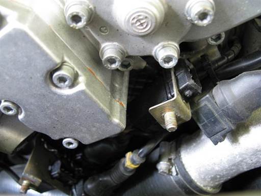
Insert solenoid electrical cable connectors into connector brackets under vanos.
Note: Connectors are keyed with brackets and will only insert in one orientation.

Connect vanos electrical cable connectors to vanos solenoid cable connectors in connector brackets.
Note: Orient intake connector metal clip down and exhaust connector metal clip out.
Press in connectors until wire clip snaps into place.

Install vanos electrical connectors cover.
Align and install cover on connector bracket studs.

Mount cover 2 nuts (10mm socket 3/8″ / 3/8″ ratchet).
Lightly tighten.

Fully tighten vanos oil pressure restrictor, ~14 Nm (by feel) (22mm open wrench).

Install vanos oil accumulator pipe.
Pull oil pipe to side and inset into vanos oil pipe hole.
Screw on oil pipe mounting bolt (12mm open wrench).
Fully tighten, 20 Nm (by feel) (12mm open wrench).
Installation of valve cover


Mount valve cover perimeter gasket and sparkplug well gaskets on engine head.
Orient sparkplug well gaskets with end bolt hole to front (picture) and perimeter ridges down.

Insert valve cover gasket two alignment dowels into respective bridge holes.

Install valve cover on engine head.
Align valve cover with engine head and gaskets and lay valve cover on engine head.
Adjust valve cover perimeter gasket so each valve cover gasket bolt hole aligns with associate valve cover perimeter bolt hole.

Install valve cover 20 mounting bolts, 16 perimeter and 4 center (10mm socket 3/8″ / 3/8″ ratchet & extension).
Note: Front center (vanos bridge) bolt and 4 center bolts are short.
Note: Rear center bolt has limited access (10mm socket 3/8″ / 1/2″ ratchet & 1/2″ to 3/8″ socket adapter (extension)).
Tighten bolts evenly working back and forth, assuring even pressure distribution on cover. Tighten until bolts bottom out on head.
Fully tighten, 8Nm (6 ft-lb) (10mm socket 3/8″ / 3/8″ torque wrench & extension).

Install valve cover ground wire w/ nut on valve cover rear most stud (picture) (10mm socket 3/8″ / 3/8″ ratchet).

Install each coil into original sparkplug well and mount with 2 nuts (10mm socket 3/8″ / 3/8″ ratchet & extension). Rotate between coil mounting nuts to mount coil evenly.
Note: Coil boot will not fully insert onto sparkplug during initial mount. This is normal.
Fully tighten, 10Nm (7 ft-lb) (10mm socket 3/8″ / 3/8″ torque wrench & extension).

Rotate coils cables/bracket/boot back onto valve cover.
Mount coil cables rear boot rubber block onto valve cover. Slide rubber block onto valve cover slot from top (picture).

Install coil cables mounting bracket.
Install bracket onto 2 mounting studs.
Install bracket 2 mounting nuts (10mm socket 3/8″ / 3/8″ ratchet & extension).

Install coil cables electrical connectors.
For each coil, lift up on connector metal lock, press in cable electrical connector, and push down on connector metal lock.
Route coil cables as needed.

Install engine top cover.
Align engine cover and place over valve cover.
Cover rear left will mount over coil cables boot rubber block. Press down on cover rear to fully mount block.
Install cover 4 mounting bolts (5mm hex bit socket 3/8″ / 3/8″ ratchet).
Installation of fan & shroud
Euro E36 M3 fan & shroud installation
Post repair procedures
Allow sealant to dry a minimum of one hour before driving car.
Check and replenish engine oil.
Drive car, then park car and let engine oil settle.
Remove oil dipstick; wipe dipstick end; fully reinsert dipstick; remove dipstick again; read oil marking. If oil is low add needed (small) amount of new oil at oil fill cap at valve cover.
© 2024 Beisan Systems LLC

