E46 M3 Fan & Shroud Procedure
The following information is provided for reference purposes only and should be used at your own risk
In no event shall Beisan Systems, LLC or its members be liable for incidental, consequential, or special loss or damages of any kind however caused.
Fan & shroud removal
Open front hood.
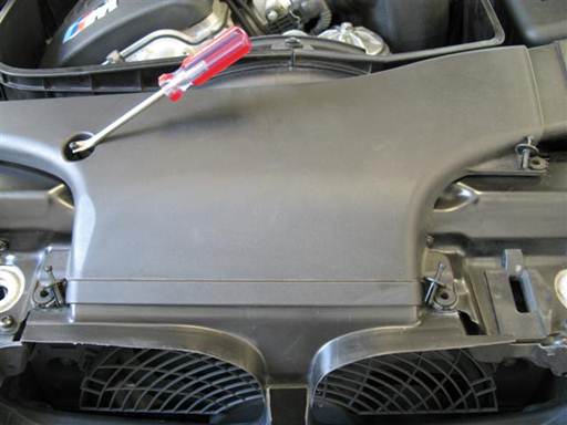
Remove 4 rivets at top of air intake duct at top of radiator.
For each rivet, pry out center pin (tack lifter), then fully pry out rivet from base (tack lifter).
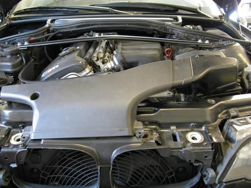
Lift up and remove air intake duct from engine bay.
Note: Air intake duct will disconnect from air filter housing.
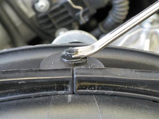
Remove shroud air guide rivet at shroud top.
Pry out rivet center pin (tack lifter), then fully pry out rivet from base (tack lifter).
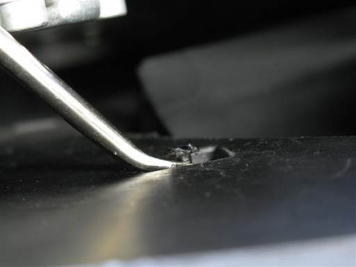
Remove left air guide rivet at rear face of air guide.
Pry out rivet center pin (tack lifter), then fully pry out rivet from base (tack lifter).
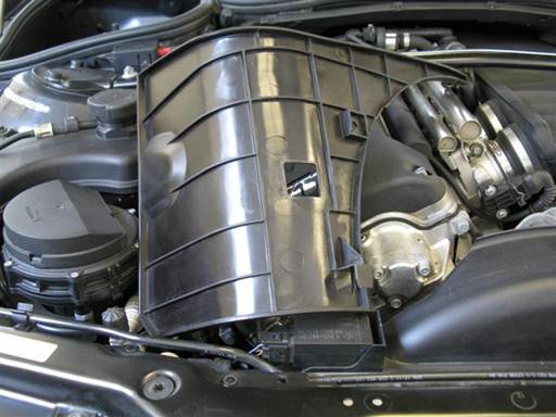
Remove left air guide.
Push left air guide to rear to release from mounting bracket.
Pull up and remove air guide from engine bay.
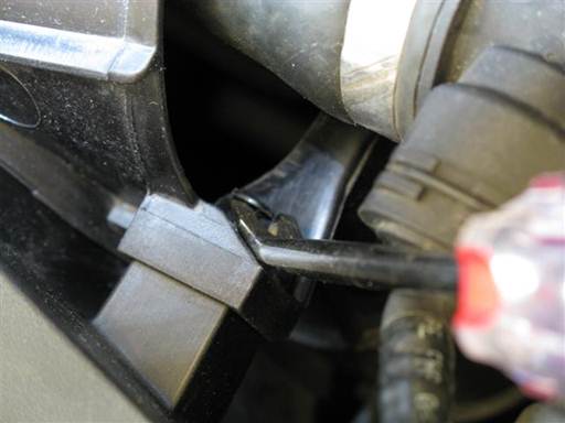
Remove right air guide rivet at right side of guide.
Pry out rivet center pin (tack lifter), then fully pry out rivet from base (tack lifter).
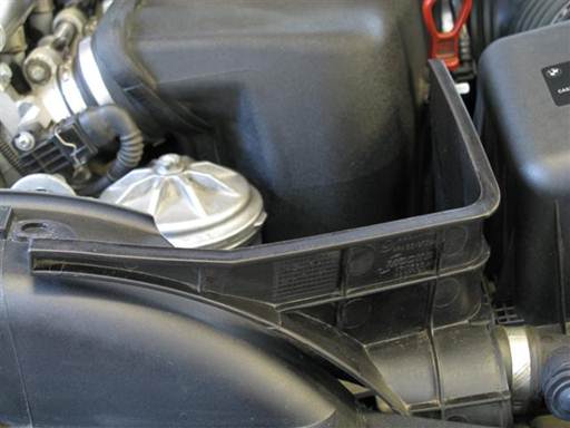
Remove right air guide from fan shroud.
Push right air guide to rear to release from mounting bracket.
Lift up air guide to release lower mounting tab.
Let air guide suspend on radiator upper hose.
Note: Radiator upper hose runs through hole in air guide and thus air guide cannot be removed without removing upper radiator hose and loosing coolant. Repair can be performed with air guide suspended on upper radiator hose.
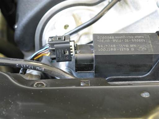
Disconnect AUC (smell) sensor electrical connector at top left of fan shroud.
Press in on connector top clip and pull out connector.
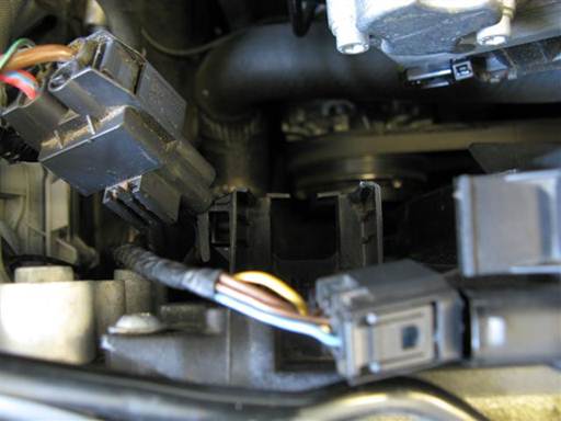
Remove auxiliary electric fan cable connectors from fan shroud bracket.
Remove cable from bracket side tabs then pull connectors up and out of bracket.
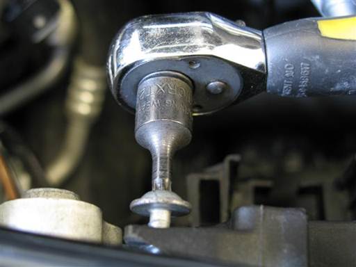
Remove fan shroud mounting bolt at top left of fan shroud (T25 torx bit socket 1/4″ / 1/4″ ratchet).
Note: Bolt is longer than other similar bolts to be removed.
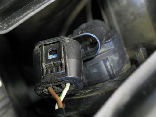
Remove right side light bulb cable electrical connector.
Press in connector clip and remove connector.
Note: Removing connector is needed for access space in next step.
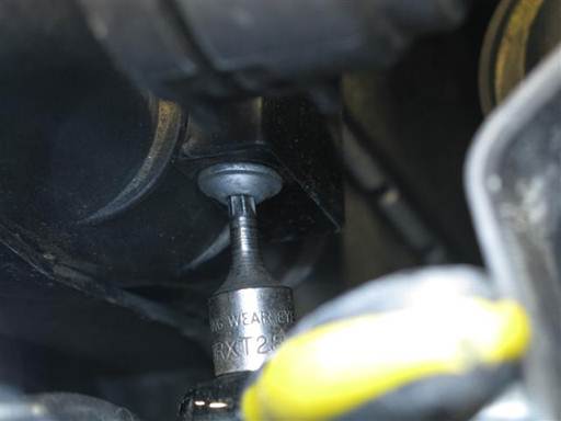
Remove fan shroud mounting bolt at top right side of fan shroud (T25 torx bit socket 1/4″ / 1/4″ ratchet).
Raise front of car and place on jack stands (follow appropriate procedure; chock both sides of both rear wheels).
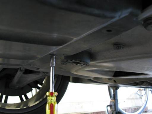
Remove engine compartment shield 3 rear mounting bolts (8mm 1/4″ / 1/4″ driver).
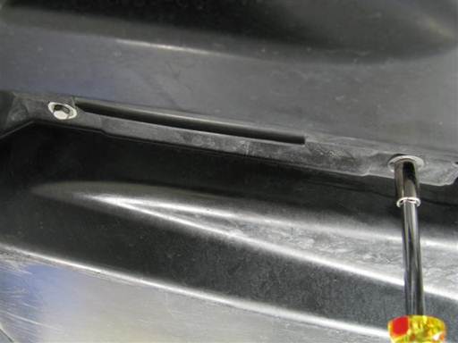
Remove engine compartment shield 2 mounting bolts at right and left side of shield (8mm 1/4″ / 1/4″ driver).
Remove engine compartment shield.
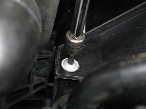
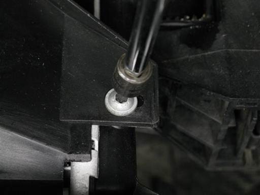
Remove fan shroud bottom left and right mounting bolts (T25 torx bit socket 1/4″ / 1/4″ ratchet & extension).
Lower car from jack stands (follow appropriate procedure).
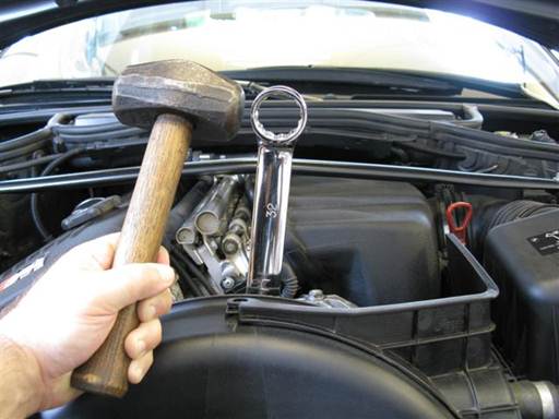
Remove fan, belt static friction method.
Remove fan / fan clutch from water pump shaft.
Place open wrench on fan clutch nut (32mm combo wrench). Place wrench forward on nut to avoid hitting thermostat hose.
Strongly strike wrench side at top with heavy hammer to break nut seize (sledge hammer); left hand thread.
Note: Nut is left hand thread, thus unscrew by hitting wrench top from left to right (car front orientation). Serpentine belt static friction on water pump pulley facilitates large enough opposing force to break nut seize. It is important to use a heavy hammer to produce a high instantaneous jerk. Several attempts will be needed before nut seize breaks. Rotate open wrench to reposition for better access.
If belt static friction method is not successful, attempt pulley holding tool method.
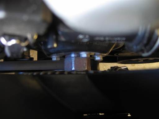
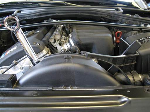
Remove fan, pulley holding tool method.
Remove fan / fan clutch from water pump shaft.
Position water pump pulley for holding tool access. Water pump pulley has 2 (adjacent) pairs of mounting bolts. Position one of the bolt pairs with left bolt at just to right of top center (picture) (32mm combo wrench).
Place air guide to side (picture).
Install water pump pulley holding tool onto pulley bolts. Position holding tool at right, and place tool indent curve against fan clutch nut. Mount tool end hole onto pulley bottom left bolt, and tool second hole onto pulley right bolt. Reposition fan clutch nut for better holding tool access (picture).
Place open wrench on fan clutch nut (32mm combo wrench). Counter hold holding tool and break clutch nut seize (32mm combo wrench); left hand thread.
Note: Nut is left hand thread, thus unscrew by turning wrench from left to right (car front orientation).
If fun clutch nut seize difficult to break, apply lubricant to nut/threads contact surfaces (spray lubricant).
Once nut seize is broken, remove tools and spin fan blades to unscrew nut; left hand thread.
When nut is close to shaft end, turn fan slowly while continuously holding fan blades. This will keep fan from falling and damaging radiator fins when fully disconnected.
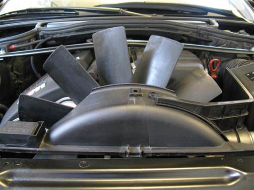
Remove fan/clutch from fan shroud.
Place right air guide to right and front.
Lift fan shroud up while maneuvering fan/clutch out of fan shroud and engine bay.
Note: Rotate fan to facilitate better positioning.
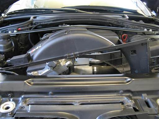
Remove fan shroud from engine bay.
Place right air guide to left and rear.
Push fan shroud to left and pull up fan shroud right side.
Push fan shroud to right and pull up fan shroud left side.
Remove fan shroud from engine bay.
Fan & shroud installation
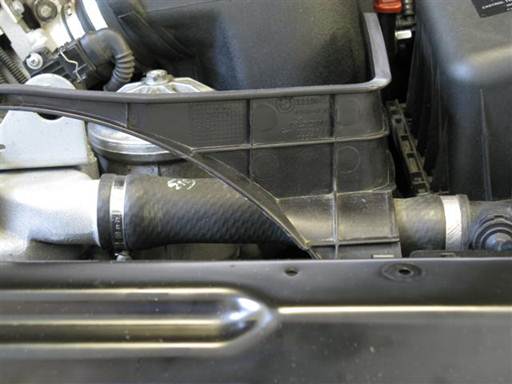
Place right air guide to left and rear.
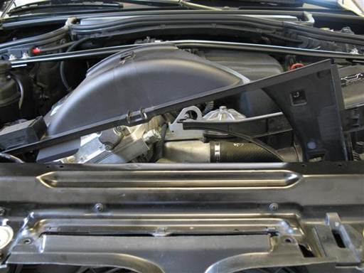
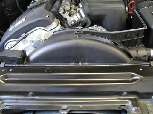
Install fan shroud in engine bay.
Push shroud to right and tilt down left side.
Push shroud to left and lower down right side.
Maneuver shroud to center and against radiator.
Mount shroud by pulling up, forward, and dropping into position.
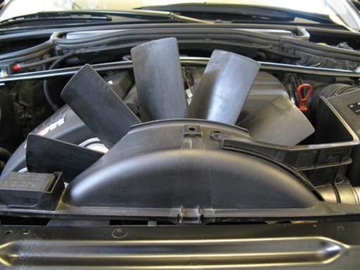
Place right air guide to right and front (picture).
Insert fan/clutch in fan shroud. Lift shroud up and forward while maneuvering fan/clutch into shroud.
Note: Fan is oriented with clutch nut to car rear.
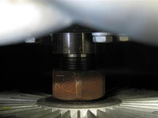
Mount fan/clutch onto water pump shaft.
Lift fan and mate (hang) fan clutch nut onto water pump shaft. Rotate fan to find best nut thread to shaft thread mate. At optimal fit, fan will hang on shaft without threading (picture).
With fan hanging independently on shaft, slowly turn fan blades to thread nut onto shaft; left hand thread. Fully thread nut onto shaft.
Fully mount shroud by pulling up, forward, and dropping down into left side frame slot.

Place open wrench on fan clutch nut (32mm combo wrench) and lightly hit wrench top with heavy hammer, one time; left hand thread (sledge hammer).
Note: Serpentine belt static friction on water pump pulley facilitates large enough opposing force to tighten clutch nut. Fan opposing spin also tightens fan clutch nut.

Install fan shroud mounting bolt at top right side of fan shroud (T25 torx bit socket 1/4″ / 1/4″ ratchet).
Note: Shroud right mounting bolt is short.
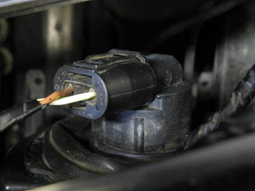
Install right side light bulb cable electrical connector.
Press in connector until clip snaps into place.
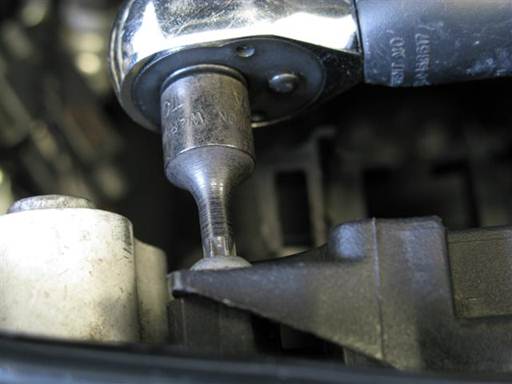
Install fan shroud mounting bolt at top left of fan shroud (T25 torx bit socket 1/4″ / 1/4″ ratchet).
Note: Shroud left mounting bolt is long.
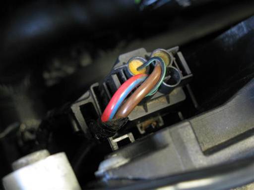
Install auxiliary electric fan cable connectors in fan shroud bracket.
Pull connectors up and insert into bracket.
Install cable in bracket side tabs.
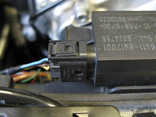
Install AUC (smell) sensor electrical cable connector at top left of fan shroud.
Press in connector until clip snaps into place.
Raise front of car and place on jack stands (follow appropriate procedure; chock both sides of both rear wheels).


Install fan shroud bottom left and right mounting bolts (T25 torx bit socket 1/4″ / 1/4″ ratchet & extension).
Insert engine compartment shield into front bumper and align into install position.
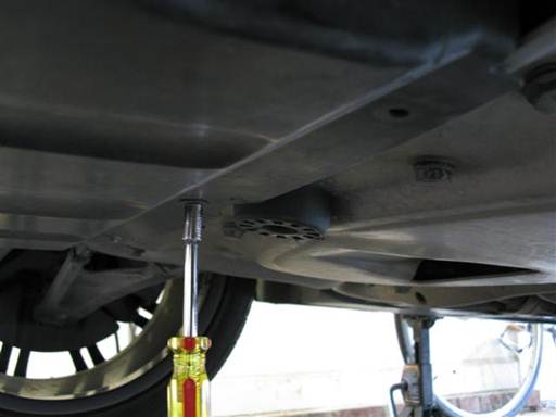
Install engine compartment shield 3 rear mounting bolts (8mm 1/4″ / 1/4″ driver).
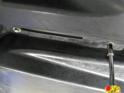
Install engine compartment shield 2 mounting bolts at right and left side of shield (8mm 1/4″ / 1/4″ driver).
Lower car from jack stands (follow appropriate procedure).
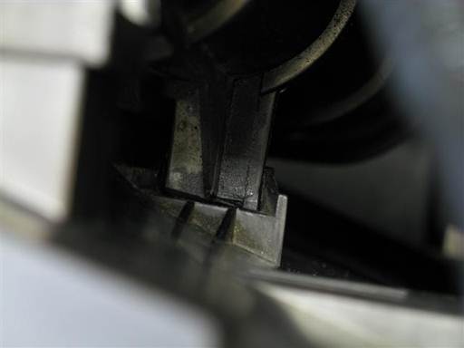
Insert right air guide lower hook into shroud slot.
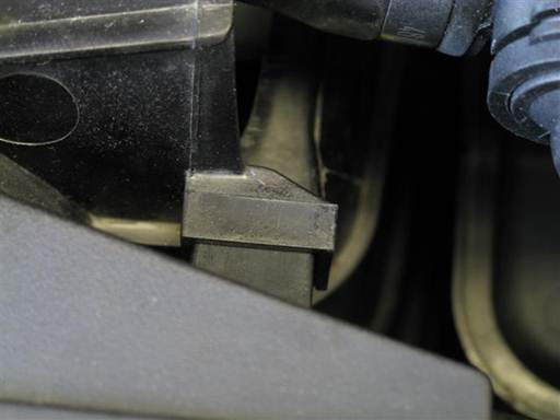
Press right air guide forward and insert guide square hole onto shroud bracket.
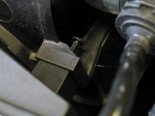
Install rivet at right air guide bracket.
Pry rivet center pin out, fully insert rivet base into air guide and shroud, then press in rivet center pin.
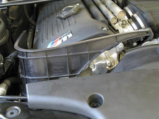
Insert shroud left air guide into place.
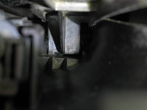
Insert guide right lower hook into shroud slot.

Press guide forward and insert guide square hole onto shroud bracket.

Install rivet at rear face of left air guide.
Pry rivet center pin out, fully insert rivet base into air guide and shroud, then press in rivet center pin.

Align left and right shroud air guides at shroud top center.
Install rivet at shroud top center. Pry rivet center pin out, fully insert rivet base into right and left guides and shroud, then press in rivet center pin.

Install air intake duct on top of radiator.
Insert duct into air filter housing.

Install 4 rivets at top air intake duct. For each rivet, pry rivet center pin out, fully insert rivet base into air intake duct, then press in rivet center pin.
© 2024 Beisan Systems LLC

